Manual for A1200 Bifrost, Heimdall Edition v1.0 - March 2020
Contents of this Manual
Introduction
- Disclaimer
- Welcome
- What is the Bifrost?
- Original LED Board
What is in the box?
- A1200 Bifrost, Heimdall Edition
- 4-pin Connection wire
- 1-pin Connection wire
- Diffuser holder
- 3x Long Diffusers for T1 cases
- 3x Short Diffusers for T1 cases
- 3x Long Diffusers for T2 cases
- 3x Short Diffusers for T2 cases
- Bleed Shield
- PCMCIA Signal Enabling Kit
Installation
- Board Pinouts
- Installing the Bleed Shield (optional)
- Installing the Diffusers
- Installing the Bifrost itself
- Installing the 4-pin lead
- Adding the extra 1-pin power lead (optional)
Using and Programming the Bifrost
- General Operation
- Entering and Exiting Configuration Mode
- Navigation Indicator Lights
- Selecting rows
- Selecting columns
- Iterating colours (up and down)
- Iterating brightness (up and down)
- Inverting lights
- Toggling the Filter/Reset Power LED dimming
- Toggling between 1 and 2 LED Modes (Basic Mode only)
- Saving configurations
- Loading configurations
- Factory Reset
Extended Mode
- An extra third LED on each channel
- Additional Brightness Levels (Thats like the Sun!)
- NO Hot- or Jumpwiring of the XVCC and PWR!
- Beware of Heat Death!
Disclaimer
The A1200 Bifrost, Heimdall Edition, is a keyboard LED replacement board for the Commodore Amiga 1200 computer. It is a third
party custom product and not endorsed by nor affiliated with the Amiga or Commodore brands, companies, or owners thereof.
Use this product at your own risk. It may irreversibly damage your computer (though I have tried really hard for it not to!).
You need to disassemble your computer in order to install this product.
The producer of this product cannot be held liable for any damage caused by the installation or usage of this product.
Welcome
First of all; Greetings and thank you for supporting The Bifrost Project and this product! You are now the owner of an
A1200 Bifrost, a fully customizable Amiga 1200 keyboard LED replacement board. I sincerely hope you will enjoy using it as much as
I enjoyed developing it!
What is the Bifrost?
The Bifrost board is a direct keyboard LED replacement board for your Amiga 1200 computer. It uses some of
the latest cutting edge technology to bring you an updated, fully feature packed and highly customizable
cosmetic experience for your beloved retro computer, available literally at your fingertips. Customize the POWER-,
FLOPPY- and HARDDRIVE LEDs to any colours and brightness of your choice using the LEDs themselves as programming buttons.
You can also choose from pulsating effects as well as colour cycling effects.
Each channel comes with three LEDs and all LEDs are individually programmable. All in all you will find
that the A1200 Bifrost, Heimdall Edition, can deliver over 150 million colour and brightness combinations to EACH
channel making the Bifrost a great choice for putting that personal touch to your Amiga machine.
The A1200 Bifrost, Heimdall Edition, also supports PCMCIA signal and/or up to three custom devices on separate
input channels, utilizing a secondary indicator layer on each of the LED rows. Furthermore, the A1200 Heimdall
supports the new CAPS LOCK Bifrost module not allowing for any original lights to escape user customization.
The original LED board
The original LED board is ANALOG meaning it has properties that the DIGITAL Bifrost does not.
If the Amiga isn't working properly the LEDs on the keyboard can sometimes display various error codes. Even though
the Bifrost is also designed to do this, I would recommend that you keep the original LED board around just in case
you would need it for some advanced troubleshooting that the Bifrost might not catch.
The box that the Bifrost came in is a perfect place to store it!
What is in the Box?
A1200 Bifrost, Heimdall Edition, Board
This is the central unit of the whole setup. This is where all the magic happens!
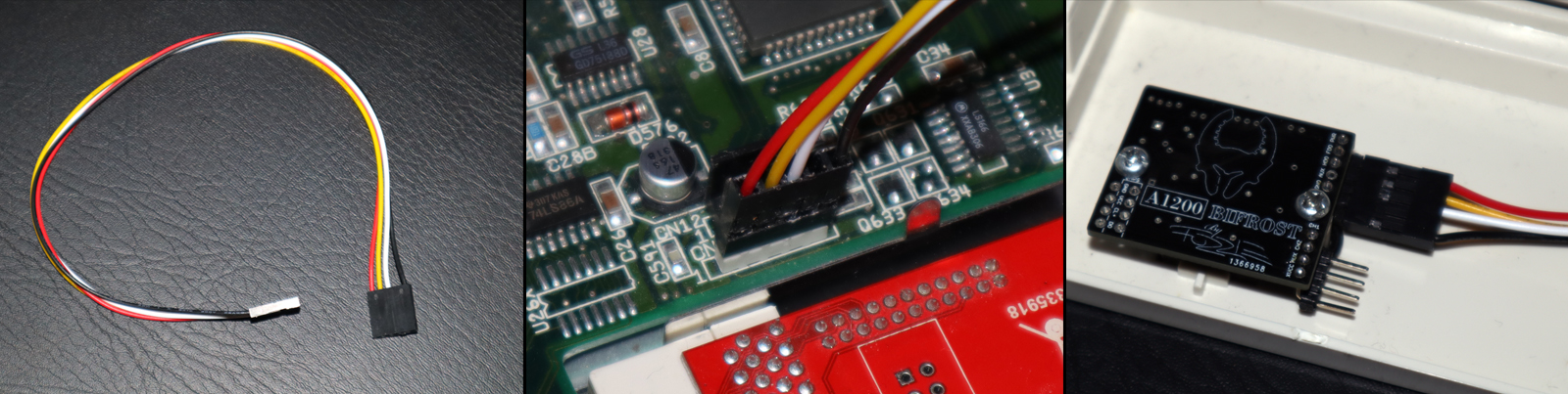
4-pin Connection wire
This is the cable that you need in order to feed the Bifrost with power and basic device signals. It has only 4 wires put on a
5-pin connector, just as the original wire. Connect this between the Bifrost 5-pin connector and the motherboard LED
connector (CN14), taking note of the keyed/blocked holes to keep the cable properly oriented.
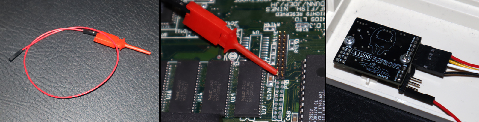
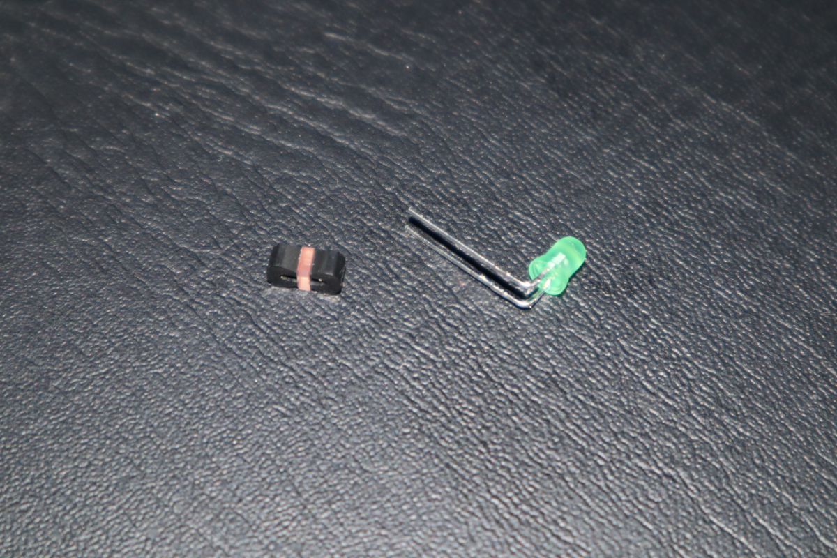
1-pin Connection wire with Probe Clip (optional)
This is an optional cable you can use to feed the Bifrost with more power than it could normally draw from just the original
motherboard LED connector (CN14). This enables "Extended Mode". Connect it on the Bifrost to pin XVCC and on the motherboard to any shared +5V rail. Use it with or without the Probe Clip at your convenience.
WARNING: Make sure you ONLY connect this to a shared +5V rail with a common GND or you can risk damaging the Bifrost itself and/or your computer. If you are
unsure about anything concerning this installation do NOT use this feature! If you DO decide to use it you understand that you do so at your own risk.
Diffuser Holder
This is a small black plastic frame. It makes sure your diffusers are kept on top of the Bifrost board and
that light sources and microswitches aligns properly. This piece is already glued to your Bifrost board when it arrives.
3x Long Diffusers for T1 cases
These diffusers are 13mm wide and a bit taller than the normal(short) diffusers. With a long diffuser you can
use your fingers directly to program your colours as it protrudes a bit up from the rest of the case. The
tall T1 diffusers are marked with T1L (T1 Long).
3x Short Diffusers for T1 cases
These diffusers are 13mm wide and of normal height. With a short diffuser you need some kind of pressing tool, like a flat
screwdriver, to be able to reach and program your colours as the diffusers are only the same height as the case and tricky to reach. The
short T1 diffusers are marked with T1S (T1 Short).
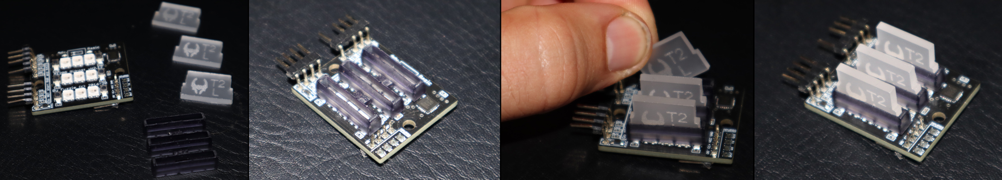
3x Long Diffusers for T2 cases
Same as it's T1 counterpart, but a little wider at 14mm. The long T2 diffusers are marked with T2L (T2 Long).
3x Short Diffusers for T2 cases
Same as it's T1 counterpart, but a little wider at 14mm. The short T2 diffusers are marked with T2S (T2 Short).
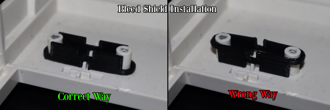
Bleed Shield (optional)
The Bleed Shield is an optional black plastic piece that stops light emission from one row of LEDs to bleed into and pollute
it's neighbouring row(s). The original Amiga does not have this, so if you are going for the original look you don't have to use it. If
you are, however, looking for that enhanced crisp and clean look then the Bleed Shield will be the thing you are looking for.
PCMCIA Signal Enabling Kit (optional DIY)
The original Amiga was designed to be able to cater to PCMCIA activity. However, because of cost efficiency decisions the few
components that would have made this possible were dropped and never placed on the motherboard. This kit contains those components
as an optional extra.
WARNING: You need ample electronics and soldering skills to install this kit. It can potentially damage the Bifrost and/or your computer.
If you are unsure about anything concerning this installation do NOT use this feature! If you DO decide to use it you understand that you do so at your own risk.
CL Bifrost Module (optional)
A small module that replaces the original Caps Lock LED in your original Amiga Keyboard. This module makes it possible to also
control and program the Caps Lock light in the same way as the other LEDs using the Bifrost.
Installation
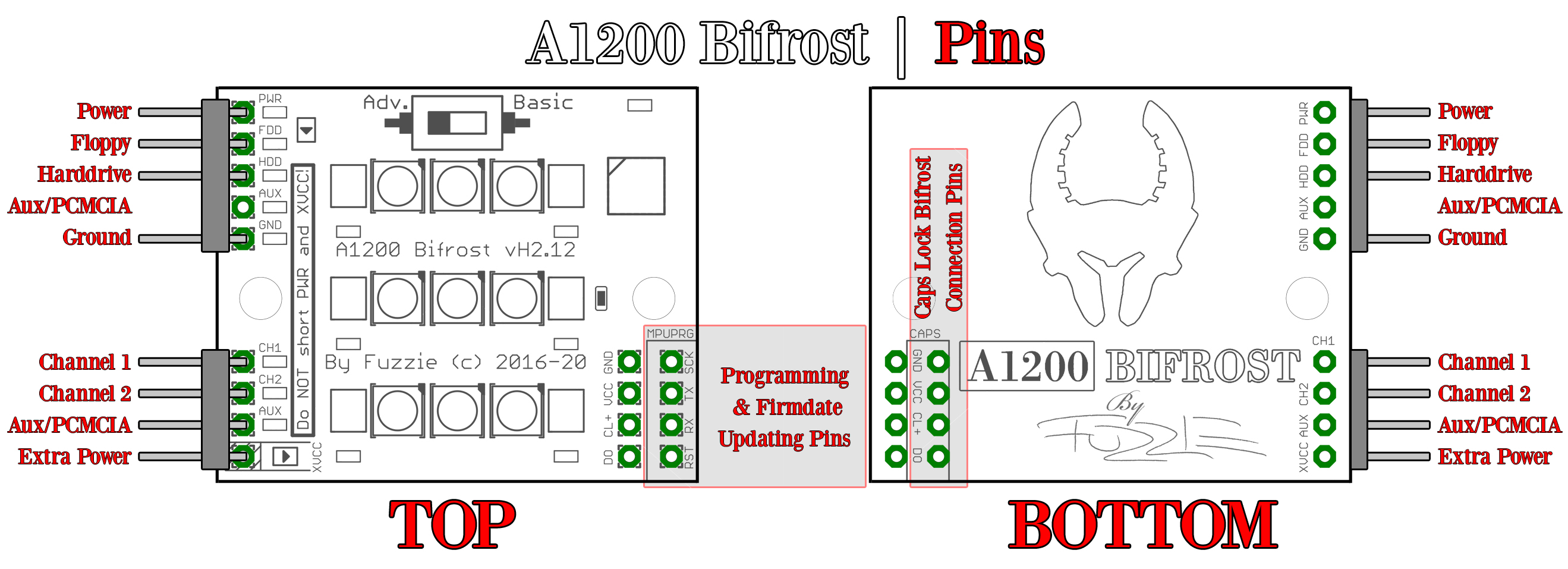
Board Pinout
To understand the board hardware better and how to connect it all up with your computer and devices
it is important to familiarize yourself with and understand what Pins do what and what goes where. Take a moment to study this pinout map,
and feel free to come back to it anytime and use it as reference.
NOTE: The following section of the manual is only for Version 1.0 (the non-combined discontinued version) of the Bleed Shield and Diffuser Holder. Skip this section if you have the combined version.
Installing the Bleed Shield (optional)
Included with early boards; If you are opting to use the Bleed Shield it needs to go in first. Gently slide it ontop and around
the protruding plastic pylons that carry the screwholes for the PCB fastening screws on the Amiga case. Make
sure that the collar of the Bleed Shield is lying towards the case itself, and not towards the PCB.
Installing the Diffusers
The Diffuser Holder should already be glued to your board (in the picture below it is not because of transparency showing off all components).
All you have to do is to select the model of diffusers you want to use, all the same ones or any mix of them if you feel wild and crazy, and place them into the slots of that Diffuser Holder.
The diffusers are supposed to be able to move freely in the frame and "rattle about" in there. This makes
sure there is no unwanted resistance to their mechanical movement that could otherwise prevent them from being used properly as buttons
when you program it.
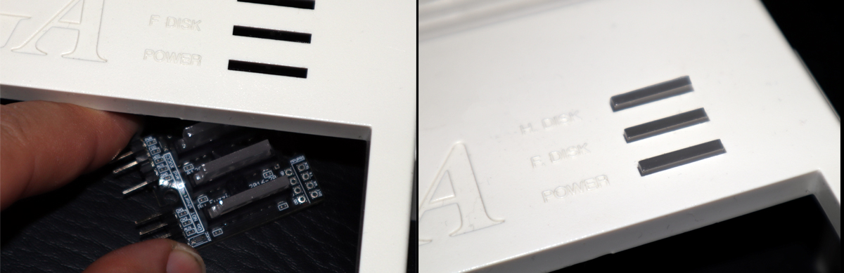
Installing the Bifrost itself
The diffusers do come off from its positioning very easily before the whole package
is in place and screwed tight. One way to install the Bifrost into the case is keeping both the case
and Bifrost upright so the diffusers don't fall off, and gently sliding it in and up in place from
underneath.
An alternative way to do it is to install the diffusers themselves first into the case slots and then the Bifrost board over them. Experiment with what works best for
you. Just remember to use a bit of care while you explore your options as the plastic diffuser frame is somewhat brittle. You NEVER have to use any force to get the Bifrost installed.
NOTE: The following section of the manual is for the current version of the Diffuser Holder with integrated Bleed Shield.
Installing the Diffuser Holder Text will update shortly.
Installing the Diffusers Text will update shortly.
Installing the Bifrost itself Text will update shortly.
Installing the 4-pin lead
The 4-lead, 5-pin connector cable is the main signal cable you need for the Bifrost to work. See it as
the equivalent of the lead of the original LED board. You can run the Bifrost with only this cable attached but the Bifrost
will then run in Basic Mode only and some of it's features will not accessible. This is because the electronics feeding the
original board is limited and the Bifrost automatically throttles down to draw less power and prevent damage to these electronics.
Adding the extra 1-pin power lead and unlocking Extended Mode (optional)
If you want to unlock the third/middle LED on each row and also all available brightness intensities then you need to put the
Bifrost in Extended Mode. You do this by attaching a separate power feed to the XVCC pin on the Bifrost using any +5V rail that
shares the same Ground. I personally use pin 20 on the Clockport (P9A) for this, but you can use any source you see fit. The
cable supplied with the Bifrost kit includes both a female header and a Probe Clip to cater to whatever setup you choose.
The Bifrost will automatically detect if it's given an extra power feed and put itself in Extended Mode.
WARNING #1: Make sure you ONLY connect this to a shared +5V rail with a common GND or you can risk damaging the Bifrost itself
and/or your computer. If you are unsure about anything concerning this installation do NOT use this feature! If you DO decide to
use it you understand that you do so at your own risk.
WARNING #2: Some of you may already see a "possibility" to fool the Bifrost into thinking it is in Extended Mode by just
hot wiring the normal power pin to the XVCC pin. DO! NOT! EVER! DO! THIS!. In Extended Mode the Bifrost can draw a significantly
larger amount of power than the original power pin is able to supply. This can result in the power pin transistor blowing out,
possibly taking more components with it in the process.
Using and Programming the Bifrost
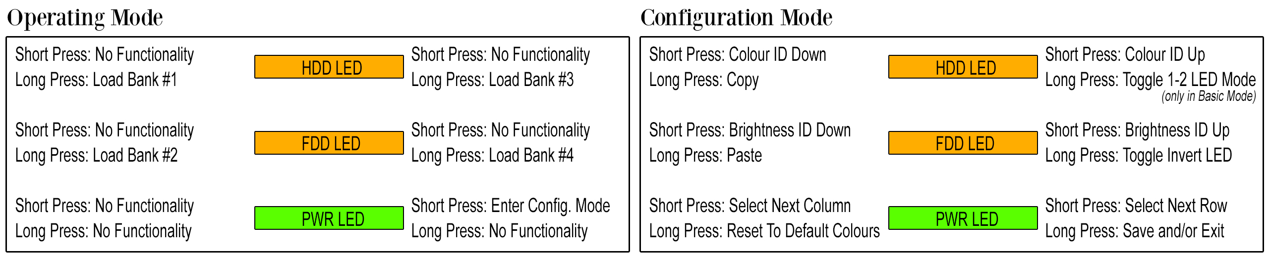
General Operations
Each edge of each LED serves as a button to program your Bifrost. With them you can choose and set colours and brightness as well as load
and save your settings, copy/paste settings between LEDs and more. Depending on if the Bifrost is in operating mode or configuration mode and whether
or not the buttons are pressed briefly or held down the buttons will have different functions.
Entering and Exiting Configuration Mode
To enter Configuration Mode you only need to press the right edge of the lower (PWR) LED briefly. The upper row will start
to shine in the colour it is programmed in and the other two will blink on their right sides. The blinking indicates you are in Configuration
Mode and the right side blink indicates you are adjusting the MAIN lights (PWR, FDD and HDD), as opposed to AUX channels (when the left
sides would blink instead). The one being lit up in it's programmed colour is your current selection.
The only exception is when you are programming the Caps Lock LED. Then only the topmost LED blinks as an indicator while the Caps Lock
LED shines it's programmed colour. If you have no Caps Lock Bifrost Module, this particular selection does nothing.
To EXIT Configuraion Mode simply hold down Save (right side of the lower LED) until it starts blinking red, release the button so it starts
blinking green, then press it again. A blue light will flash on all LEDs to indicate you that you exited without saving.
Navigation Indicator Lights
To help you through navigating settings on the Bifrost there are some key indicators built into the system that you should know about.
The LED that you have NOT selected to program will blink either to the right or to the left, and in most cases white but under some certain
circumstances in other colours as well.
If the LEDs are blinking on the RIGHT side it means you are working on the Primary Indicator Layer. This includes the
POWER, FLOPPY and HARDDRIVE signals and corresponding LEDs. If the LEDs are blinking on their LEFT side you are working on the
Secondary Indicator Layer and with signals and LEDs of the Auxiliary and PCMCIA inputs.
If these indicator lights blinks in some other colour than white you are currently at a particular colour ID. Please
refer to the Colour Chart for colours and what they mean.
Selecting Rows
To iterate through the ROWS of the Bifrost just press the right edge of the lower (PWR) LED briefly. It will iterate from the top down. If
you have already selected the lowest row and press it again you will select Caps Lock LED. If you press it once more, you will get back to the top
row.
Selecting Columns & Accessing AUX channels
To iterate throught the COLUMNS of the Bifrost just press the left edge of the lower (PWR) LED briefly. It will iterate from the right
side going left. Once you iterate to the leftmost column LED, pressing it again will select the whole row of the AUX channel on that LED, and pressing
it again will select columns of the AUX channels. While working with the AUX channels the blink indicators will shift to the left sides to indicate this.
Iterating Colours Up and Down
This could very well be the bread and butter of the whole Bifrost; selecting colours! You iterate through the colours
using the edges of the top (HDD) LED. The right edge iterates up through the colour chart, the left edge iterates back down. A few
settings have non-white blink indicators: They are RED when you have selected the Pure Red light (Colour ID=1), GREEN when
you have selected the Pure Green light (Colour ID=13) and BLUE if you have selected the Pure Blue light (Colour ID=25).
There are also special colour modes such as Rainbow Fading and Random Colour Picks in various speeds. When you have
selected a Rainbow Fade the blink indicators are Magenta and when you have selected a Random Colour Pick the blink indicators
are Cyan.
Refer to the Colour Chart available here on the right. Click it to open it up in a new window and view it in full size.
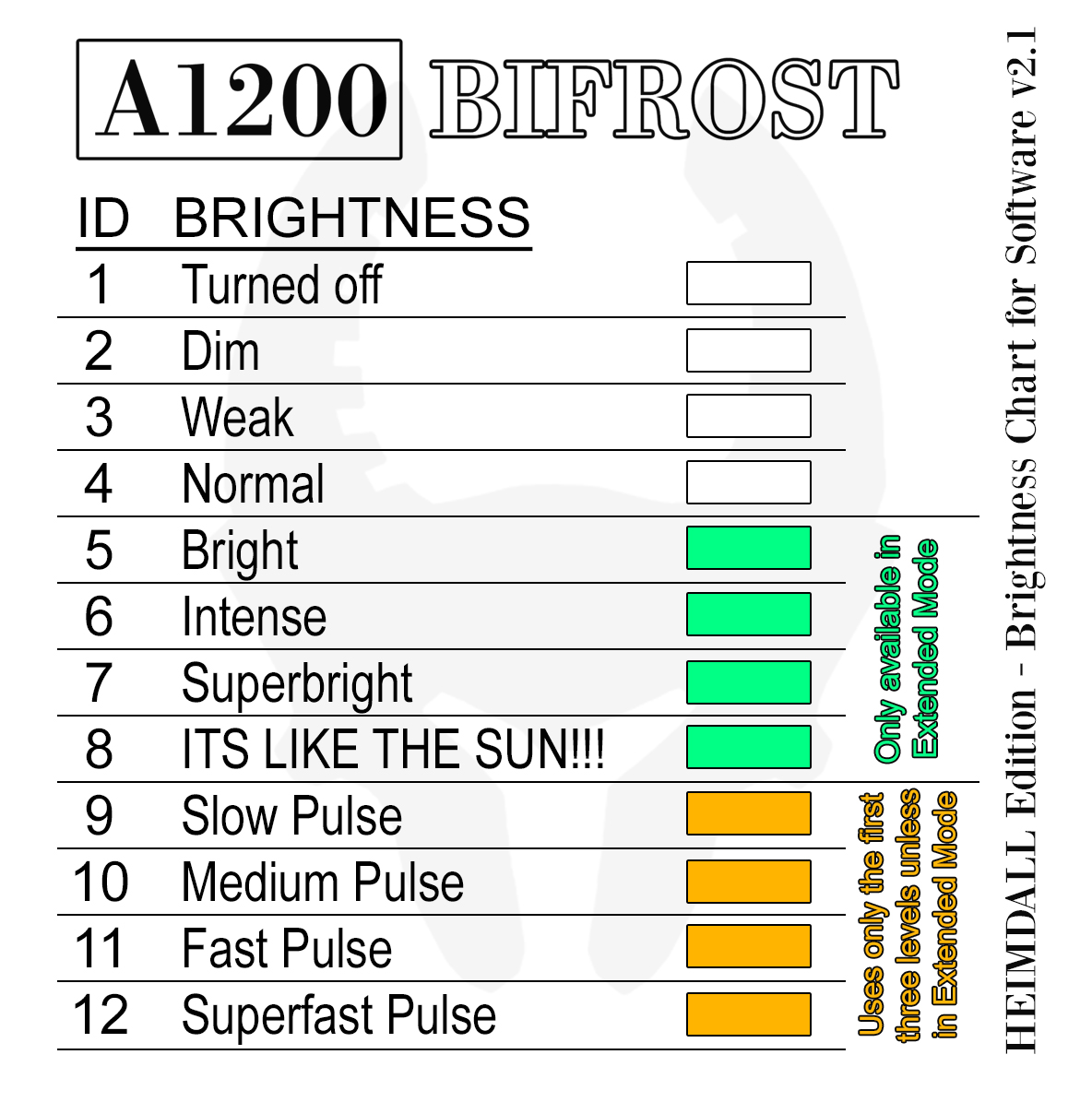
Iterating Brightness Up and Down
Itering through the various intensities is done through the edges of the middle (FDD) LED. If you are using the Bifrost
in Basic Mode (without extra power) then you will have access to only three solid brightness levels. If you are running in
Extended Mode then you will have access to seven solid brightness levels instead. Similarly, the Pulsating effects contains less
brightness level steps in Basic Mode than in Extended Mode. This restriction is in place to prevent excessive power draws from
the native power supplied by the motherboard.
You can also choose from four different speeds of Light Pulsing, or "Breathing", and if
you want to turn off a light fully you can do so by using Brightness ID=1. Refer to the Brightness Chart available
here to the right.
WARNING: The Bifrost can display Brightness Levels and Colours that cause discomforts and trigger seizures for people with
photosensitive epilepsy. User discretion is advised.
Inverting Lights
You can invert the functions on any and all LEDs. This means the LED will be on if it does not have a device signal coming in
and turn it off if it detects activity. For example, putting the FDD led in Inverted Mode means it will be lit up as normal
when you are NOT loading/saving from a Floppy and turned on solid when idling.
You do this by pressing and holding the right edge of the middle LED until it strobes up. If it strobes in GREEN it means that the
inverted mode is active. If it strobes in RED inverted mode is turned off and is operating as normal.
Inverting the AUX channels makes it possible to have different colours depending on operations. Check out the Advanced Mixing
video below for more on that in details.
Toggling the Filter/Reset Power LED dimming
If you invert the POWER LED the functionality behaviour is a bit different. That simply means turning dimming off when the
computer is soft resetting and using the sound filter. This can be desirable to do if the Bifrost is used with something else than
the Amiga, for example a RPi emulator system.
Toggling between 1-2 LED Modes (Basic Mode only)
The intended, and also preset, mode while using the Bifrost in Basic Mode is using a single LED only for each channel, the middle one.
This is done to prevent excessive power draws from the PWR PIN transistor supplying the power to the unit.
You can override the 1-LED Mode and set the Bifrost to 2-LED Mode instead if you wish, and then the edge LEDs will be used instead of
only the middle one. You do this by pressing and holding the Top Right button until all rows strobes in it's new set mode (1 or 2).
A word of caution: The 2-LED mode should be treated as an "experimental" mode in lack of better terms. The Bifrost cannot support this mode fully as, again, it
will take the neccessary steps to protect the PWR PIN transistor from excessive power draws. When using multiple colours on a LED it automatically
needs more power (treat each Red, Green and Blue component as an additional LED) and the Amiga is simply not built for handling the amount of
power needed to do this. Using more than 1 LED and all colour components on them can prove a real challenge.
Keeping this in mind some wierd phenomena could arise in 2-LED mode, such as totally different colours on the PWR LED when resetting,
and LED flickering when using random colour picking modes. It all depends on the total picture
of all settings you use. While developing I had the option to lock down this feature totally, but I did not wan't to do that. Instead I want
you to still be able to play around with and use it, but with the trade-off to these restrictions and unexpected behaviours.
If you run the Bifrost in "Extended Mode" this Button assignment will not have any functionality at all.
Saving Configurations
When you are happy with your mix settings you need to save them to a Save Bank. There are four banks in total on the Bifrost that
can hold different settings. To save just press and hold down the PWR LED on the right side until all rows starts blinking RED. This is
Bifrosts way to tell you it acknowledges your wish to save (or to Exit without saving).
Now release the Save/Exit button and the Bifrost will start blinking GREEN on all rows instead. This is to tell you that Bifrost is now
waiting for you to decide which Bank to use for these settings. Pressing Top Left will save into Bank 1, Middle Left will save into Bank 2,
Top Right will save into Bank 3 and Middle Right will save into Bank 4. When the Bifrost detects the selected bank it will start flashing on
all rows in that particular setting. Release the Bank button and the Bifrost automatically exits to Operating Mode with those settings saved
and active.
The lower row (PWR LED) does not have any Banks assigned to them. Pressing either edge of these when prompted to select a Bank will
instead exit to Operating Mode without Saving (but still keeping them active). A blue blinking light on all rows is used to indicate this.
Loading Configurations
Loading and setting the active Bank is done in Operating Mode. Simply press and
hold down the Bank Button you wish to load. Top Left will load Bank 1, Middle Left will
load bank 2, Top Right will load Bank 3 and Middle Right will load Bank 4.
The Bifrost will start blinking on all rows in the settings
it loaded from the bank you selected. Release the Bank button to stop the blinking and
return to Operating Mode. These settings are now loaded and also set to use forthwith.
Factory Reset
The default colours of the Bifrost is set to mimic the usual factory colours of the stock Amiga LEDs. They
are a shade of GREEN for PWR LED and a shade of ORANGE for the other two. The Auxiliary channels default
colours are CYAN for Channel 1 and 2, and RED for PCMCIA (or Channel 3).
You can shortcut to set these colours by pressing and holding the Lower Left LED row until
it starts blinking in those colours. Remember, if you want to save these settings and use them you
must do so by Saving as you normally would any setting (see Saving Configurations above).
Extended Mode
An extra third LED on each channel
In Extended Mode you will have access to all three LEDs in the row. This will be unlocked automagically once the Bifrost
has an extra power lead connected to the XVCC pin.
Additional Brightness Levels (Thats like the Sun!)
Also in Extended Mode all Brightness Levels (an additional 4 of them) becomes unlocked. This also affects Pulse selections
which will now use higher brightness levels over more steps than it would in Basic Mode. The highest Brightness setting
is extremely bright, and I do not recommend looking directly into this light long or, actually, at all.
WARNING: The Bifrost can display Brightness Levels and Colours that cause discomforts and trigger seizures for people with
photosensitive epilepsy. User discretion is advised.
NO Hot- or Jumpwiring of the XVCC and PWR!
This cannot be stressed enough. Using the Extra Power pin on your Bifrost unlocks all its features and is
the way it was designed to be used. However, "hacking" the Bifrost and fooling it into thinking it has additional power
by simply bypassing the extra lead and hotwiring it with the normal PWR is NOT the way to go.
The transistor on the Amiga motherboard that normally supplies power to the original LED board is only
rated at 200mA, not including age deterioration. When the Bifrost is used at it's maximum it can draw well over 600mA, three times as much as
this! The Bifrost has a built-in protection for this in Basic Mode, but that protection is dropped if the
Bifrost detects ANY power source on the XVCC pin. It doesn't know that the power is enough or not, it will draw
as much as it needs to perform all it's operations.
So... DONT. EVER. DO. THIS!
Beware of Heat Death!
Extended Mode and all it's most intense Brightnesses are fun and all that, but use it sparingly. Excessive use
of the brightest settings can make the LEDs really warm and shorten their lifespans.
Feel free to use the highest settings by all means, thats why they are there and accessable to you. Just avoid using
them actively too much such as they would be, for example, during Inverted LED Modes.
I want your Bifrost to last as long as possible, and running the unit as cold as possible is always a good idea to
achieve this.
Advanced Features
2x Custom Inputs
You will find two pins on the Bifrost labelled CH1 and CH2, Channel 1 and 2 respectively. These are
dedicated extra inputs for external devices if you would like to display their activities through the Bifrost
LEDs. Channel 1 use the Top LED and Channel 2 use the Middle LED.
These Pins will trigger on any signal between +2.7V and +5V with respect to, and that use, a common
Ground (GND) with the Bifrost and the Amiga. The Bifrost use a 10k Pull-Down resistor on these pins to clean
the signals from noise. Your signal needs to overcome this resistance technically but should generally not be a problem.
PCMCIA Input -or- 3rd Custom Input
The PCMCIA, or third Custom Input Pin, is accessable in two ways. You can reach it through either the
AUX pin on the 5-pin header, there to mainly cater to the PCMCIA signal if you choose to use it, or through
the AUX on the 4-pin header if you want to use if for something else.
These two pins are one and the same, and have no built-in protection, so do NOT use these for two
different devices at the same time!
The PCMCIA, or third Custom Input Pin, utilizes the PWR LED to indicate it's operations and trigger under
the same conditions as the other two Custom Inputs as described in the section above.
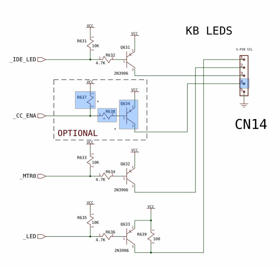
PCMCIA Signal Enabling Kit (optional DIY)
The Bifrost supports the PCMCIA device signal using the Secondary Indicator Layer on the PWR LED. Unfortunately the
Amiga motherboard does not normally have the components needed for this signal to come through to the connector
leading up to the LED board. However, the design is already there so all you need to do is to solder the required components
onto their respective slots.
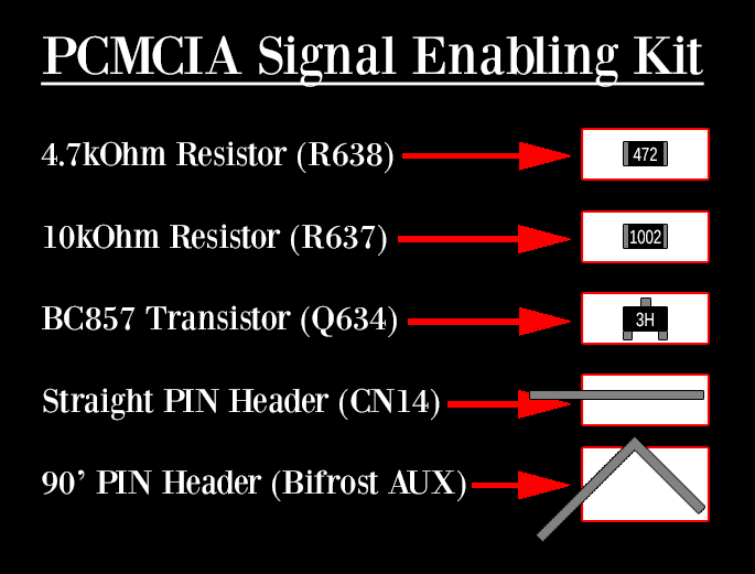
The Bifrost kit comes included with an assembly card with these components attached; a 4.7kOhm Resistor, a 10kOhm Resistor, a PNP transistor,
a straight PIN for the CN14 connector on the motherboard and a 90' angled PIN for the Bifrost 5-pin connector. Included separately is
also a wire (the Orange one) to finish off the 4-lead wire and effectively upgrading it to a 5-lead wire instead. This modified lead will
then connect the signal between the motherboard and the Bifrost properly.
Please note that this is a DIY project that requires ample soldering and electronics skills
and should not be undertaken unless you are absolutely sure you know what you do and you have the proper tools to do it.
It can damage your computer and/or the Bifrost unit so please understand you do this modification at your own risk.
The dashed box "OPTIONAL" in the left picture above is the PCMCIA schematic as it is designed on the Amiga motherboard. The components in the
blue boxes are the ones provided with the PCMCIA Signal Enabling Kit and which you need to install. Also note that you need to install
the fifth PIN on the CN14 connector on the motherboard since this was also left out.
Also, on the Bifrost side you need to install the 90' pin on the 5-pin AUX position. This
is easiest done by taking off the pin collar from the 4 pins that are already there, sliding in the new 90' pin in the AUX hole and putting
the collar back ontop of all the 5 pins, keeping the fifth pin there in position so you can solder it in place.
As for the wire, just pop out the blocking pins on both sides of the 5-pin connector using a thin long tool and pressing it from the
other direction. Then slide the crimp connectors in so it gets hooked and secured in place by the plastic lip on the connector itself.
If it doesn't stick it is probably oriented the wrong way around, try turning it 90' and put it in again. Please keep in mind that modifying
the cable this way takes away ALL orientation keys and thus it can now be installed the wrong way around. Make sure the wire is oriented
correctly before firing up your Amiga again!
Caps Lock Module (optional)
The CL Module is another optional modification you can perform to your computer. On the keyboard on the CAPS LOCK button there is an
indicator light, usually green or red, that you can replace with this module. With the CL Bifrost you will have the same modification options for that
light as you do for your other ones.
You need to disassemble your keyboard for this: Remove the keyboard from the Amiga, unscrew all the little screws on the backside of it
and lift the keyboard sandwich apart. Pay close attention to how it all fits together!
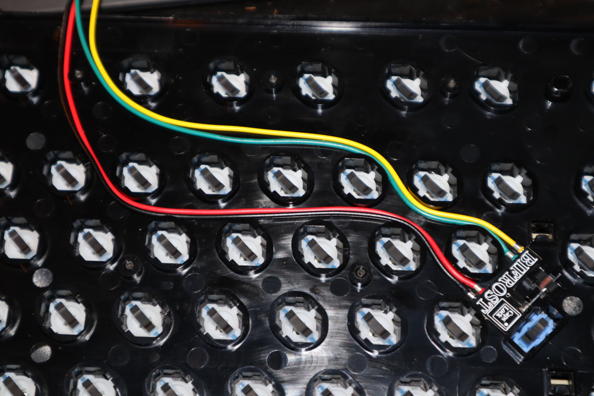
Now, with only the keyboard frame infront of you turn it around to see the "back" of all the keys. At the Caps Lock key you will find a
small traditional 3mm LED with 90' bent pins going into a rubber signal transfer piece. Take off the small rubber piece gently and slide it
ontop of the pin of the CL Bifrost module instead. As you probably already noticed the CL Bifrost have only one pin instead of the original
LEDs two, so you will be left with one empty hole in the rubber piece. The empty hole should be turned to face inwards towards the CL Bifrost
itself.
Carefully place the module into the keyboard, aligning the CAPS LOCK hole with the CL Bifrost LED and with the rubber piece back into its
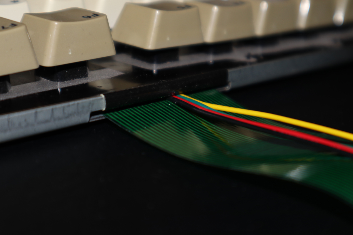
place. Navigate the cables in the empty space between the key collars and up towards and out from the same hole as the keyboard ribbon cable exits
through. Now gently place the green keyboard contact sheet back and sandwich it with the back plate. This whole cable threading procedure is a
bit complicated and time consuming to get right. Make sure all is in place properly and that cables run without being squished anywhere when you
screw the whole sandwich back together.
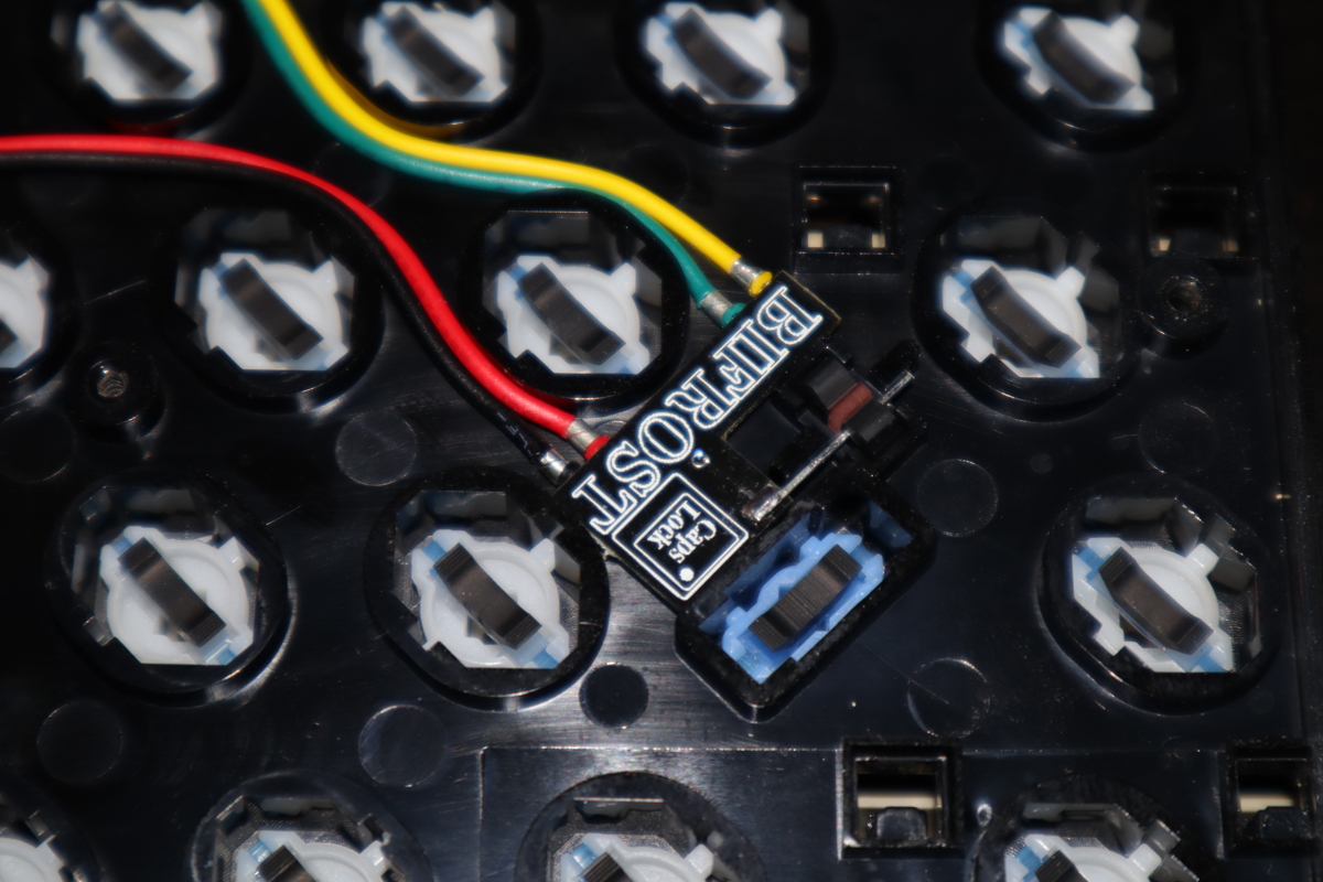
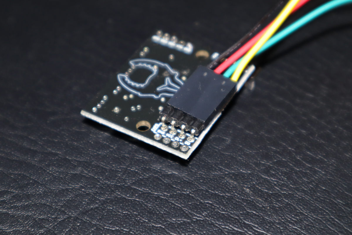
Once the keyboard is assembled back and the CL Bifrost leads go out from the keyboard ribbon cable hole place everything back and connect the
CL Bifrost up to the main Bifrost unit. Use the 90' angled connector already provided with the CL Bifrost to gently press the connector in place as
pictured below. On the main board black goes to Ground, Red goes to +5V, Green goes to CL+ and Yellow goes to DO.
Photos used with expressed permissions. If you want to use any of the pictures please inquiry with the original photographer directly.
"The Bifrost Project" and it's attached products are not endorsed by nor affiliated with the Amiga or Commodore brands, companies, or owners thereof.
The Bifrost Project™, A500 Bifrost™, A600 Bifrost™ and A1200 Bifrost™ names and logotypes are registered and/or worked in IP's 2016-2024 owned by Fuzzie Technologies®.
a500bifrost.com, a600bifrost.com, a1200bifrost.com are registered domains 2017-2024 owned by Fuzzie Technologies®.
Fuzzie Technologies® is a registered company in Sweden since 2013.