
|


|

|
|
|
Manual for A600 Bifrost (1st Gen)
v1.0 - February 2024
Please Note
This manual is under construction. Sections will be added, expanded and/or removed sporadically.
Contents of this Manual
Introduction
- Disclaimer
- Welcome
- What is the Bifrost?
- Original LED Board
What is in the box?
- A600 Bifrost
- Diffuser Assembly
- Straight pin connector
- Screw
- A600 Caps Lock Bifrost
Installation
- Board Pinouts
- Installing the Diffuser Assembly
- Installing the Bifrost itself
Using and Programming the Bifrost
- General Operation
- Entering and Exiting Configuration Mode
- Navigation Indicator Lights
- Selecting rows
- Iterating colours
- Iterating brightness
- Toggling the Filter/Reset Power LED dimming
- Saving configuration
- Factory Reset
Advanced Features
- 1x Custom Input (optional)
- Caps Lock Module (optional)
|
|
Introduction
|
|
Disclaimer
The A600 Bifrost is a keyboard LED replacement board for the Commodore Amiga 600 computer. It is a third
party custom product and is not endorsed by nor affiliated with the Amiga or Commodore brands, companies, or owners thereof.
Use this product at your own risk. It may irreversibly damage your computer (though I have tried really hard for it not to!).
You need to disassemble your computer in order to install this product.
The producer of this product cannot be held liable for any damage caused by the installation or usage of this product.
|
|
|
Welcome
First of all; Greetings and thank you for supporting The Bifrost Project and this product! You are now the owner of an
A600 Bifrost, a fully customizable Amiga 600 keyboard LED replacement board. I sincerely hope you will enjoy using it as much as
I enjoyed developing it!
|
|
|
What is the Bifrost?
The Bifrost board is a direct keyboard LED replacement board for your Amiga 600 computer. It uses some of
the latest cutting edge technology to bring you an updated, fully feature packed and highly customizable
cosmetic experience for your beloved retro computer, available literally at your fingertips. Customize the POWER-,
FLOPPY- and HARDDRIVE LEDs to any colours and brightness of your choice using the LEDs themselves as programming buttons.
You can also choose from pulsating effects as well as colour cycling effects.
Each channel comes with an individually programmable LED. All in all you will find
that the A600 Bifrost can deliver over 100.000 unique colour and brightness combinations making the Bifrost a great choice for putting that personal touch to your Amiga machine.
The A600 Bifrost also supports an additional custom signal utilizing a secondary indicator layer mappable to a LED of your choice (default PWR). Furthermore, the A600 Bifrost
supports the new CAPS LOCK Bifrost module not allowing for any original lights to escape user customization.
|
|
|
The original LED board
The original LED board is ANALOGUE meaning it has properties that the DIGITAL Bifrost does not.
If the Amiga isn't working properly the LEDs on the keyboard can sometimes display various error codes. Even though
the Bifrost is also designed to do this, it is not very accurate and I would recommend that you keep the original
LED board around just in case you would need it for some advanced troubleshooting that the Bifrost might not catch.
The box that the Bifrost came in is a perfect place to store your original board when not using it!
|
|
What is in the Box?
|
|
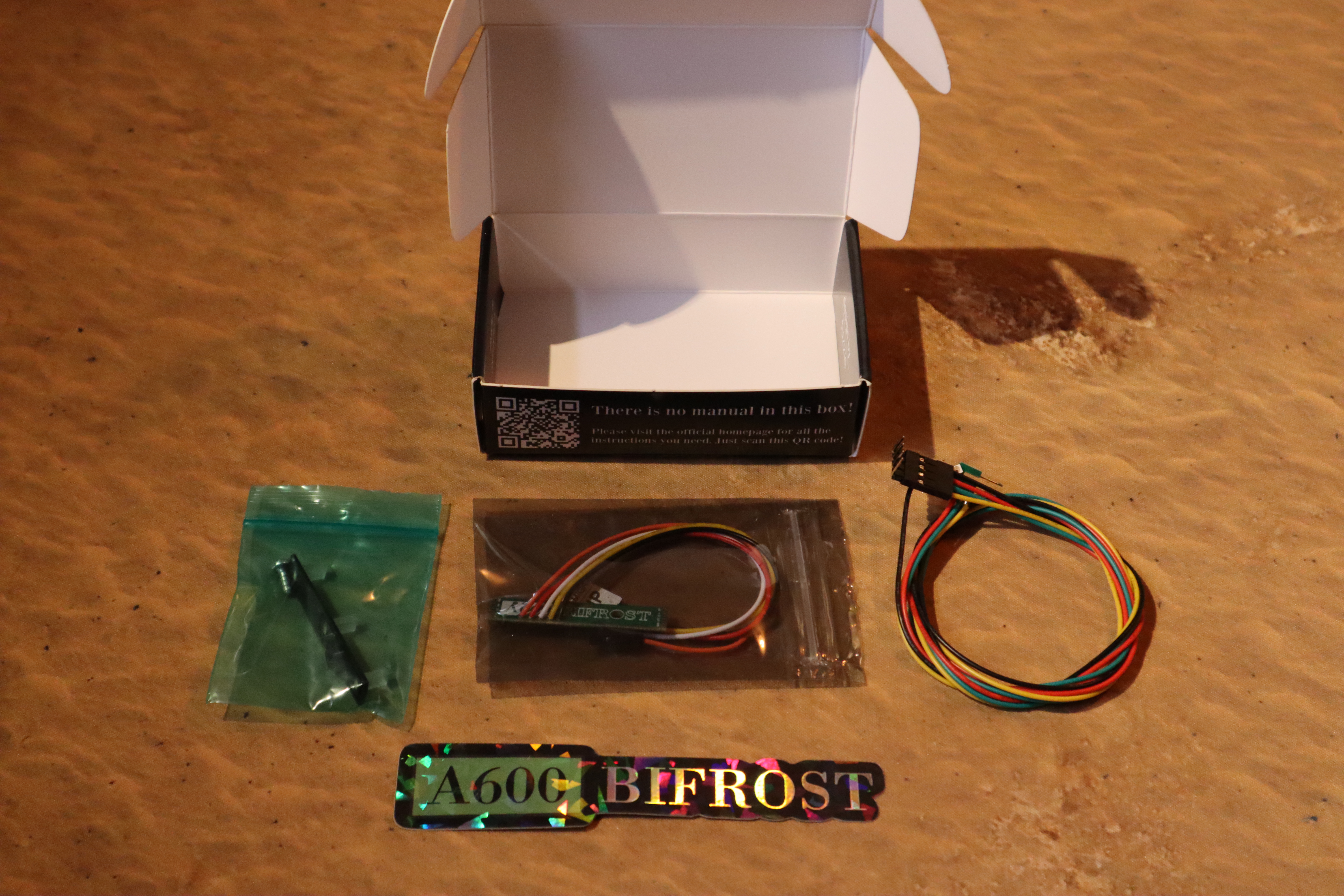
A600 Bifrost Board
This is the central unit of the whole setup. This is where all the magic happens!
Diffuser Assembly
This is a small black plastic frame with the three Diffuser light guides attached to it.
Straight Pin Connector
This is a small straight header pin used for scenarios where one is needed for the custom AUX channel.
Screw
In most cases the original screw holding the old LED-board in place will be just fine to reuse. However, I have noticed in some cases that the original screw is too short. So the supplied extra screw
is slightly longer than those original screws to accomodate a secure fit for the A600 Bifrost comparatively thicker construction.
A600 Bifrost Caps Lock Module (optional)
A small module that replaces the original Caps Lock LED in your original Amiga Keyboard. This module makes it possible to also
control and program the Caps Lock light in the same way as the other LEDs using the Bifrost.
|
|
|
Installation
|
|
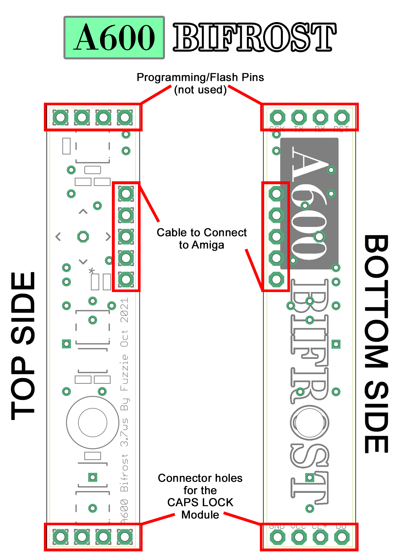
Board Pinout
To understand the board hardware better and how to connect it all up with your computer and devices
it is important to familiarize yourself with and understand what Pins do what and what goes where. Take a moment to study this pinout map,
and feel free to come back to it anytime and use it as reference.
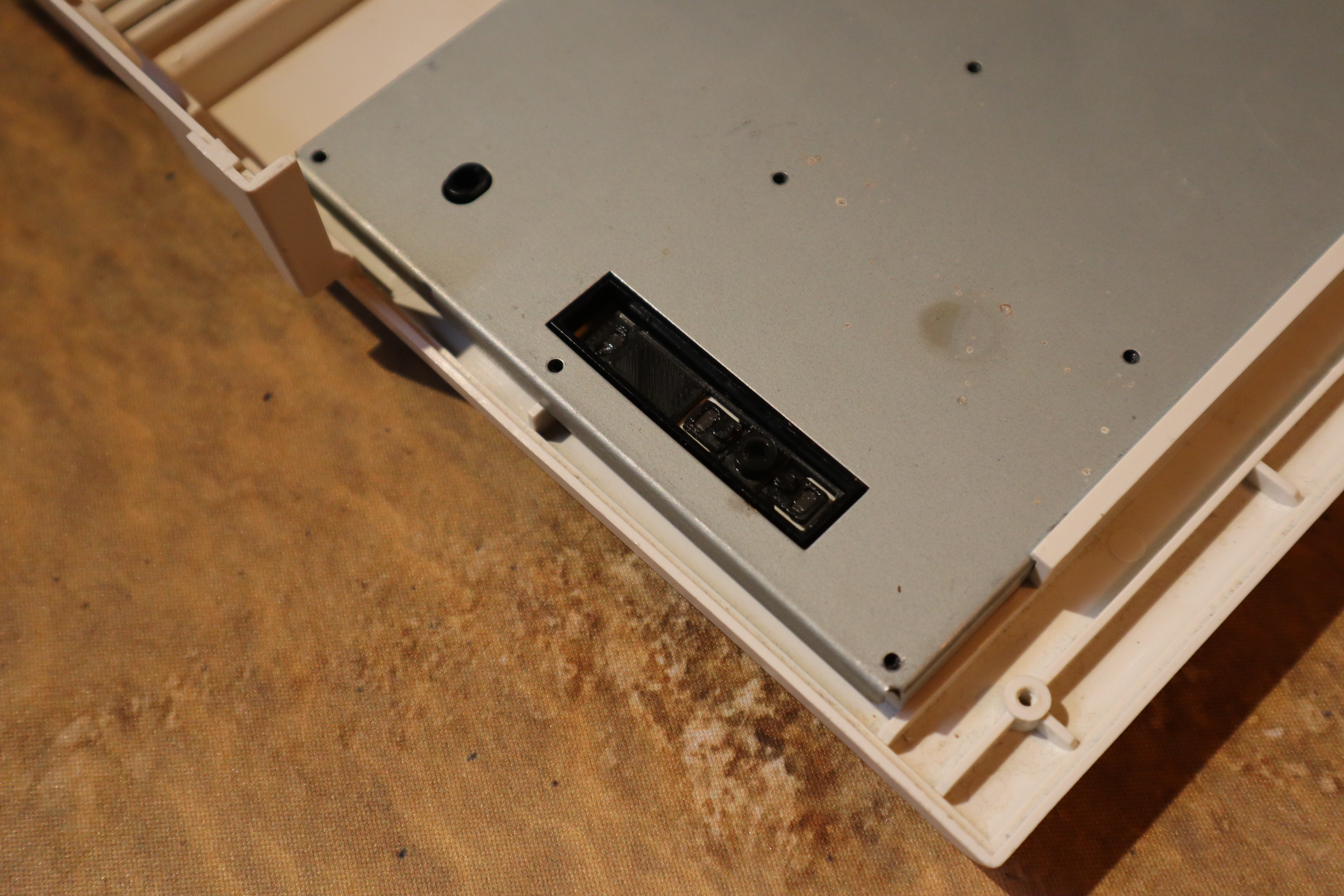
Installing the Diffuser Assembly
Just pop the Diffuser Assembly in from the back of the top half of the Amiga case. It should fit snuggly into the three diffuser compartments and the hole to attach the screw should align properly.
The diffusers should be able to move freely in the diffuser alcoves and "rattle about" in there. This makes
sure there is no unwanted resistance to their mechanical movement that could otherwise prevent them from being used properly as buttons when you program it.
Installing the Bifrost itself
Install the Bifrost board itself on top of the Diffuser Assembly, making sure it aligns up properly with the screw hole and tight it down firmly with the provided or the original screw.
Please use caution here, as tightening it too tight will auto-press the configuration buttons. In fact it is quite beneficial to even leave the board a bit loose. My tip to you is to tighten it down
carefully and then just releasing the screw back just a little. It will leave the whole board sitting a bit loosely but I think this is more positive than negative.
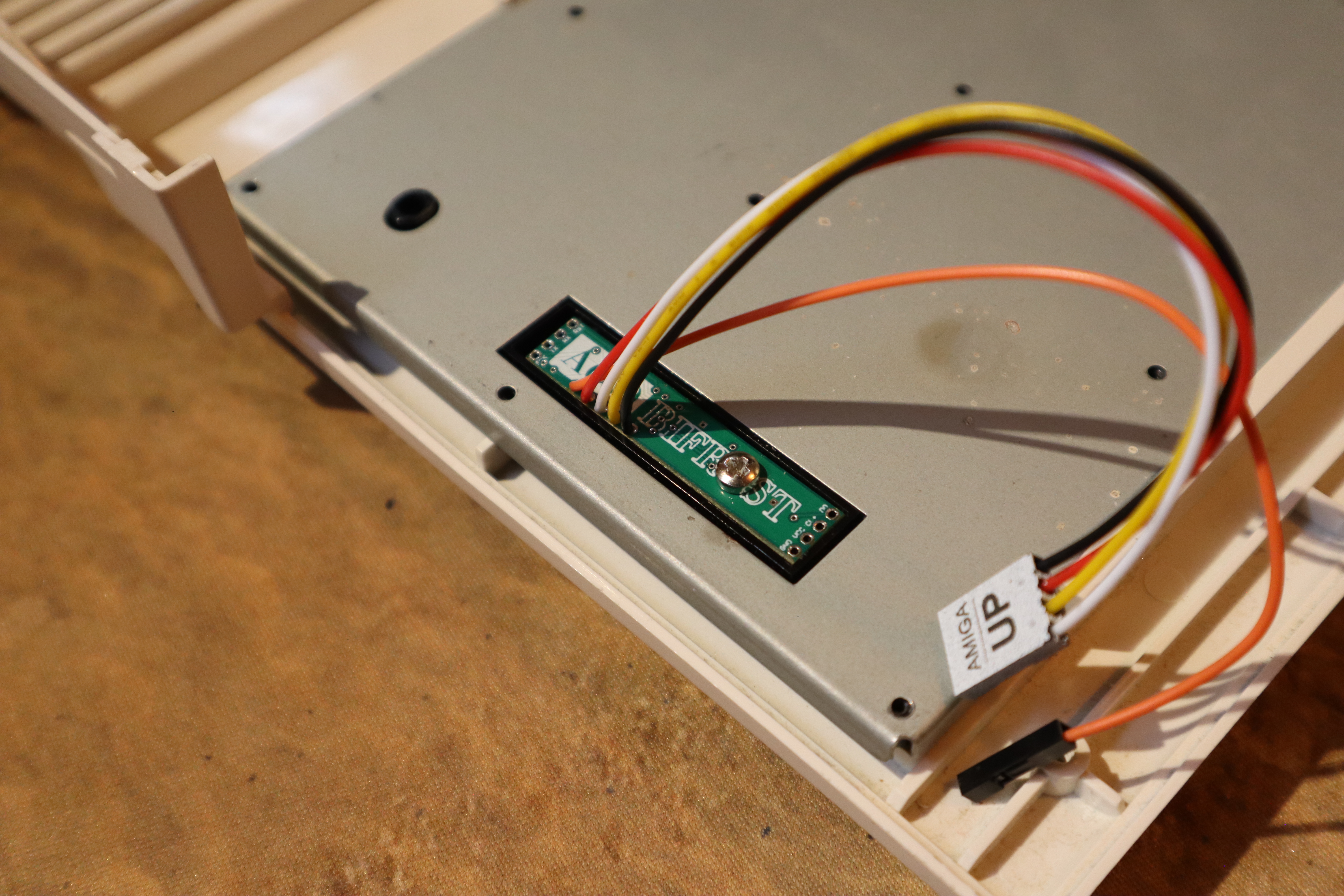
Another great tip I can give you is to press with your finger on either side of the screw and see if you can hear a small "click"-sound from the buttons. If you do, that is great and everything
will most likely work perfectly. If you cannot hear any clicks at all, just try to loosen the screw a tiny bit more.
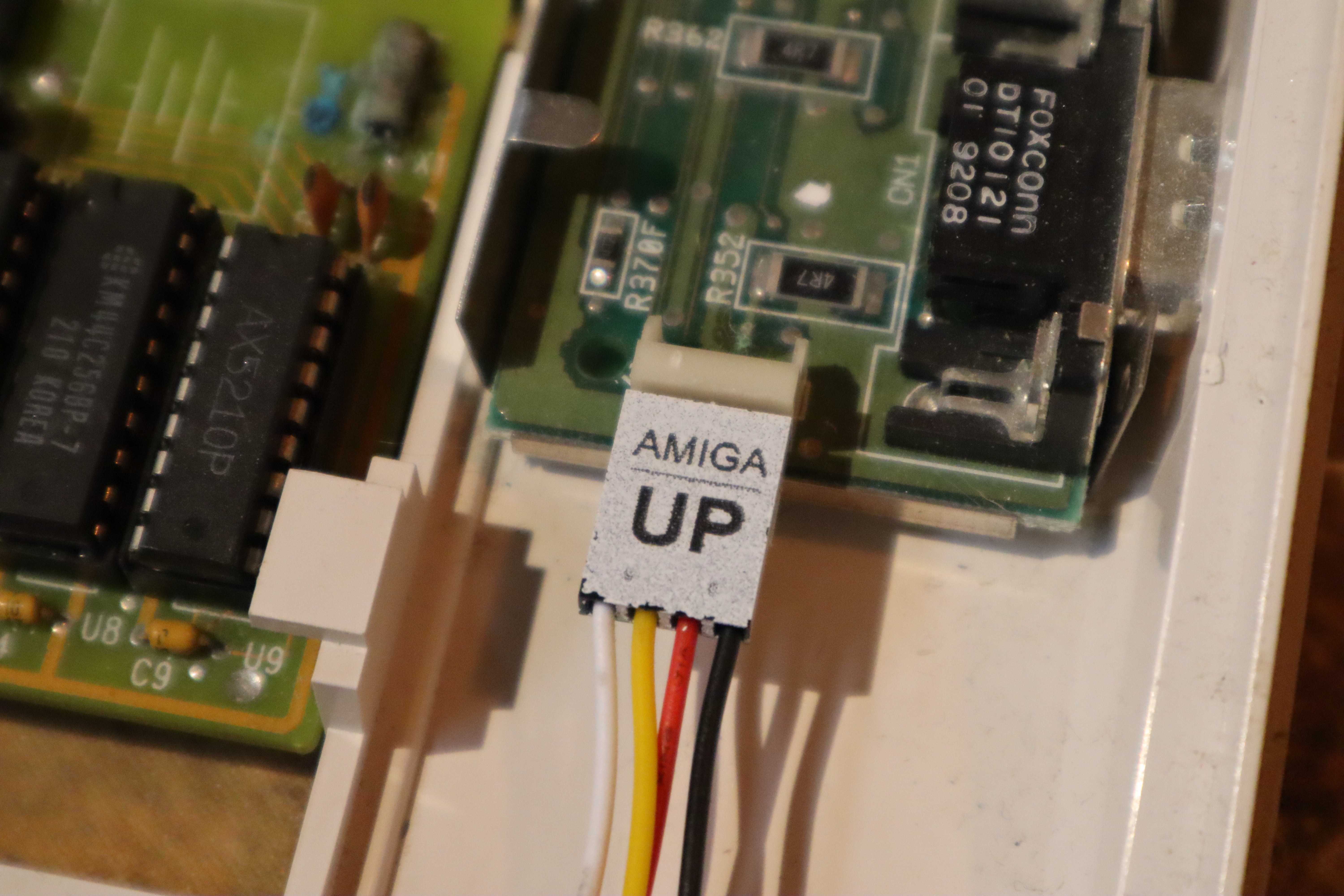
Installing the 4-pin lead
The 4-lead connector cable is the main signal cable you need for the Bifrost to work. See it as
the equivalent of the lead of the original LED board. Install it with the connector side saying "AMIGA UP" face up and visible to you.
WARNING: Make sure this is connected the correct way and side up. The Bifrost is extremely sensitive and will most likely break immediately if this is not connected correctly. You also risk
damaging your Amiga!
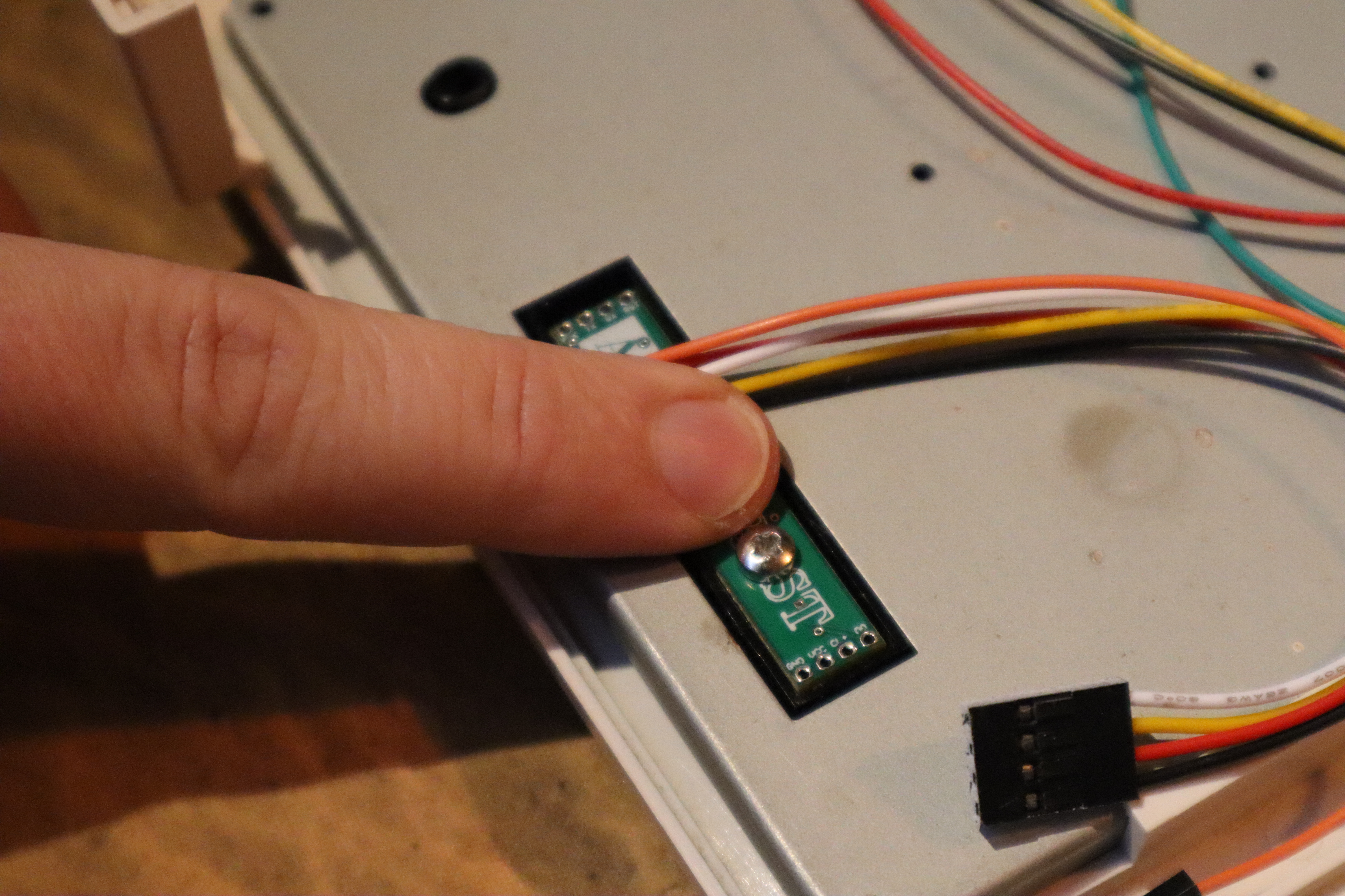
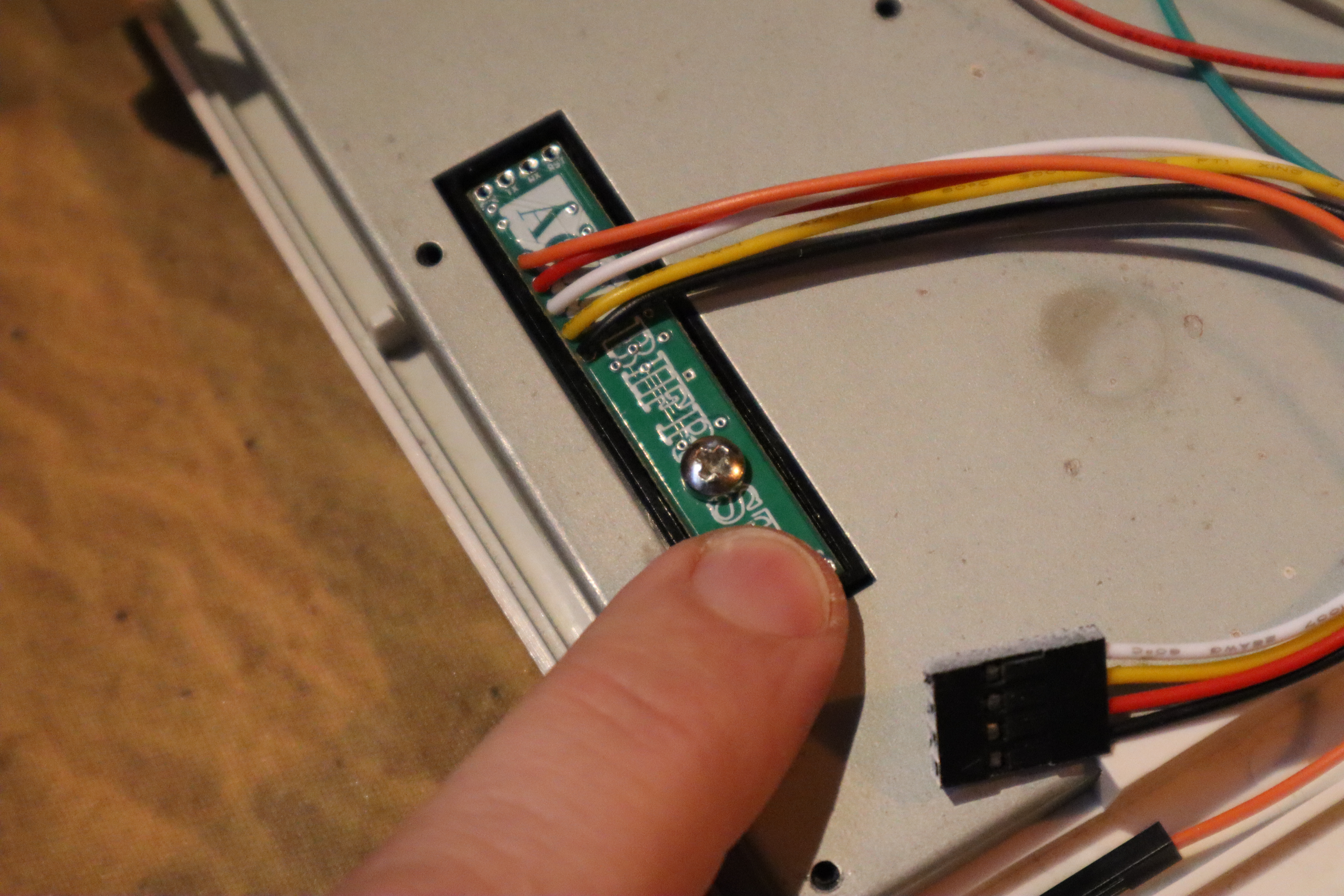
Installing the 1-pin lead (optional)
The 1-pin lead is for your custom -or- AUX channel. Whatever can give you an active signal to indicate operation can be connected to this, provided the voltage is between 2.7V and 5V and it
shares common GND with the Bifrost. The complementary straight pin header supplied with the kit can be used to bridge this with another female connector if need be.
WARNING: Do not use the straight pin header attached if you do not connect it further to a device. This will only increase the risk of this connector coming into contact with something
inside your computer that it is not supposed to touch, and stuff may break.
|
|
|
Using and Programming the Bifrost
|
|
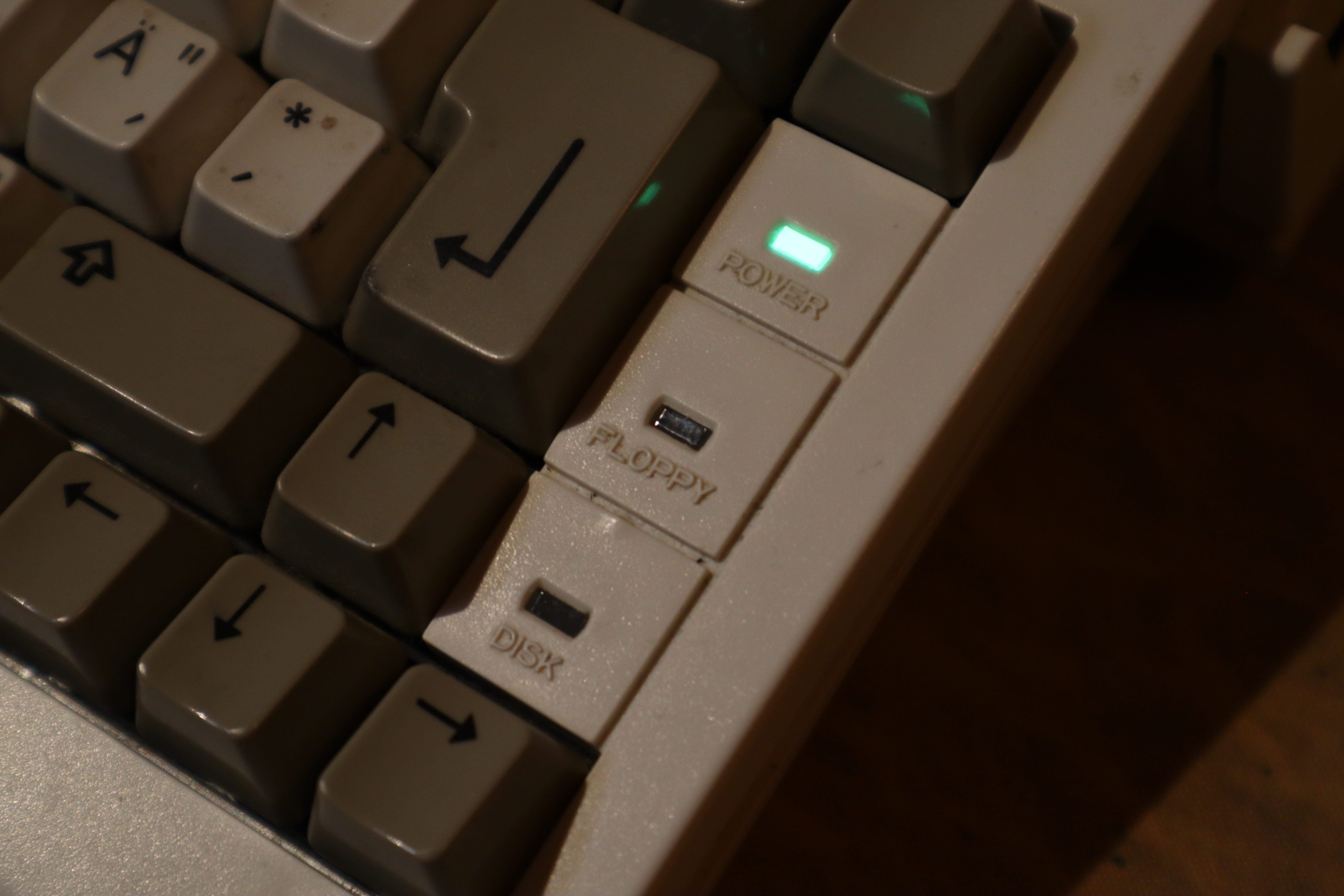
General Operations
The bottom/lower (DISK) and middle (FLOPPY) LEDs also serves as buttons to program your Bifrost. With them you can choose and set colours and brightness as well as save
your settings. Depending on if the Bifrost is in operating mode or configuration mode and whether
or not the buttons are pressed briefly or held down the buttons will have different functions.
General Operations Cheat Sheet
Below you can find a handy Cheat Sheet for when you are programming your Bifrost. Click it to open it as a larger version in a new window.
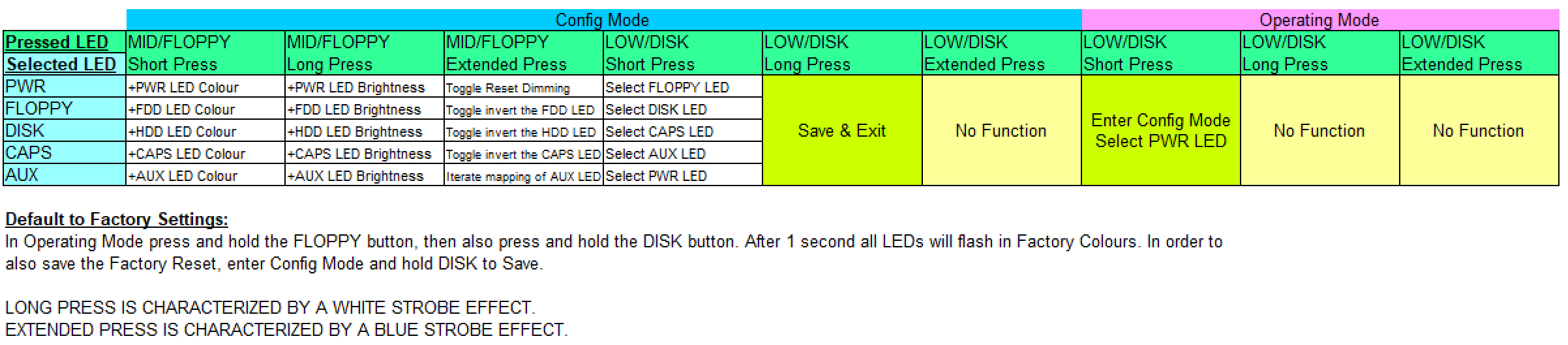
Entering and Exiting Configuration Mode
To enter Configuration Mode you only need to press the bottom/lower (DISK) LED briefly. The upper row will start
to shine in the colour it is programmed in and the other two will blink. The blinking indicates you are in Configuration
Mode. The one being lit up in it's programmed colour is your current selection.
If you are programming the Caps Lock LED all three "normal" LEDs will blink as an indicator while the Caps Lock
LED shines it's programmed colour. If you have no Caps Lock Bifrost Module, this particular selection appears to, and will, do nothing.
One more step after selecting the Caps Lock module you are choosing the AUX channel. The AUX channel will shine it's designated LED (default PWR) in the colour it is programmed in while the others
blink as normal in Config Mode.
To EXIT Configuraion Mode simply hold down Save (bottom/lower LED) until all LEDs starts blinking in the colours they are programmed in. Release the button and your config is saved and the board
returns automatically to normal Operation Mode instead.
Navigation Indicator Lights
To help you through navigating settings on the Bifrost there are some key indicators built into the system that you should know about.
The LED that you have NOT selected to program will blink, and in most cases white but under some certain
circumstances in other colours as well.
If these indicator lights blinks in some other colour than white you are currently at a particular colour ID. Please
refer to the Colour Chart for colours and what they mean.
Selecting Rows
To iterate through the ROWS of the Bifrost just press the bottom/lower LED briefly. It will iterate from the top down. If
you have already selected the lowest row and press it again you will select Caps Lock LED. If you press it once more, you will select the AUX channel and if you press yet one more time
you will get back to the top row.
Iterating Colours
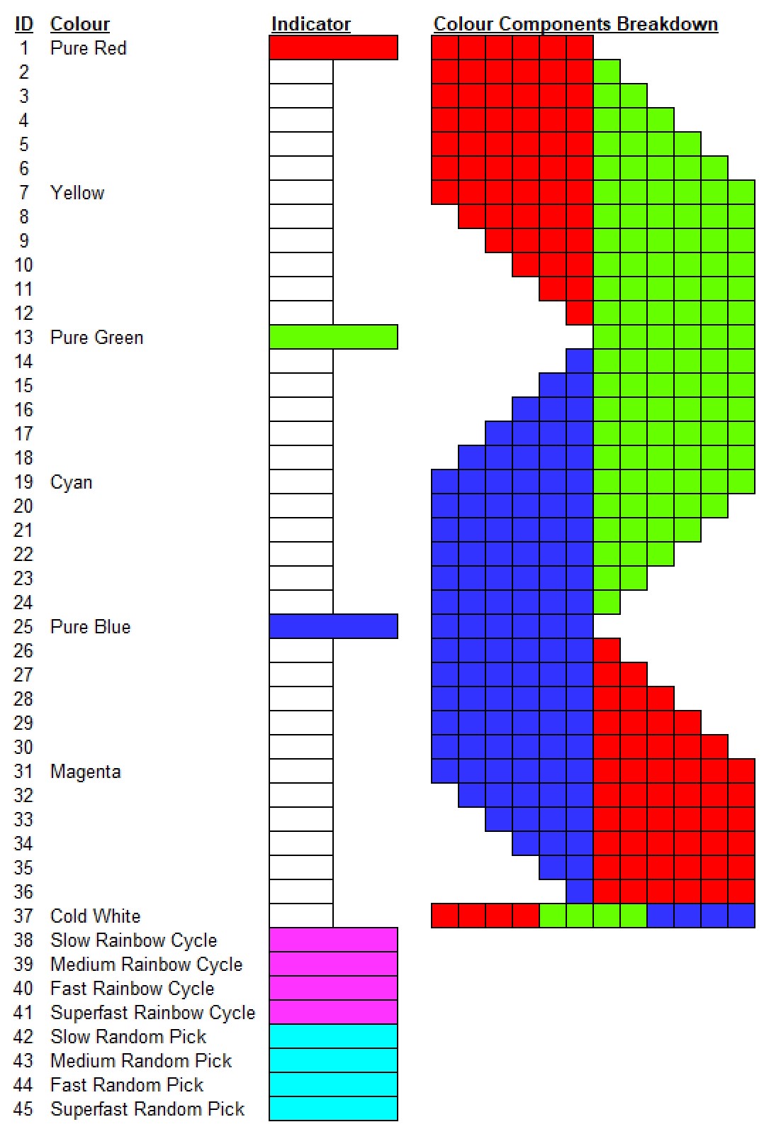 This could very well be the bread and butter of the whole Bifrost; selecting colours! You iterate through the colours
using brief presses of the middle LED. A few
settings have non-white blink indicators: They are RED when you have selected the Pure Red light (Colour ID=1), GREEN when
you have selected the Pure Green light (Colour ID=13) and BLUE if you have selected the Pure Blue light (Colour ID=25).
This could very well be the bread and butter of the whole Bifrost; selecting colours! You iterate through the colours
using brief presses of the middle LED. A few
settings have non-white blink indicators: They are RED when you have selected the Pure Red light (Colour ID=1), GREEN when
you have selected the Pure Green light (Colour ID=13) and BLUE if you have selected the Pure Blue light (Colour ID=25).
There are also special colour modes such as Rainbow Fading and Random Colour Picks in various speeds. When you have
selected a Rainbow Fade the blink indicators are Magenta and when you have selected a Random Colour Pick the blink indicators
are Cyan.
Refer to the Colour Chart available here on the right. Click it to open it up in a new window and view it in full size.
Iterating Brightness Intensities & Inverting Lights
 Itering through the various intensities is also done through the middle LED, but using a LONG press instead. When a LONG press has been detected the LEDs will strobe to indicate you have iterated the Brightness setting. Release it before an EXTENDED press occurs or you will instead Invert the LED.
You can also choose from four different speeds of Light Pulsing, or "Breathing". Refer to the Brightness Chart available
here to the right.
Itering through the various intensities is also done through the middle LED, but using a LONG press instead. When a LONG press has been detected the LEDs will strobe to indicate you have iterated the Brightness setting. Release it before an EXTENDED press occurs or you will instead Invert the LED.
You can also choose from four different speeds of Light Pulsing, or "Breathing". Refer to the Brightness Chart available
here to the right.
WARNING: The Bifrost can display Brightness Levels and Colours that cause discomforts and trigger seizures for people with
photosensitive epilepsy. User discretion is advised.
Toggling the Filter/Reset Power LED dimming
If the PWR LED is selected and you EXTEND press the middle LED (Holding the button down beyond a LONG press) you toggle the POWER LED Filter/Reset dimming on and off. If the indicator LEDs strobe
GREEN it means it is turned on. If it strobes RED it is turned off. This replaces the Invert LED function on this LED.
Saving Configurations
When you are happy with your mix settings you need to save them. To save just press and hold down the bottom/lower LED until all rows starts blinking in their programmed colours.
Now release the Save button and the Bifrost will return to normal Operation Mode with the new settings.
Factory Reset
The default colours of the Bifrost is set to mimic the usual factory colours of the stock Amiga LEDs. They
are a shade of GREEN for PWR LED and a shade of ORANGE for the other two. The AUX channel default
colour is RED.
You can shortcut to set these colours by pressing and holding the middle LED and then also press and hold the lower LED until the whole unit
starts to blink in those colours. This ONLY works in OPERATING MODE!
Remember, if you want to save these settings and use them you must do so by Saving as you normally would any setting (see Saving Configurations above).
|
|
Advanced Features
|
|
1x Custom Input
You will find and extra lead on the Bifrost. This is a
dedicated extra input for external devices if you would like to display their activities through the Bifrost
LEDs.
This Pin will trigger on any signal between +2.7V and +5V with respect to, and that use, a common
Ground (GND) with the Bifrost and the Amiga. The Bifrost use a 10k Pull-Down resistor on these pins to clean
the signals from noise. Your signal needs to overcome this resistance technically but should generally not be a problem.
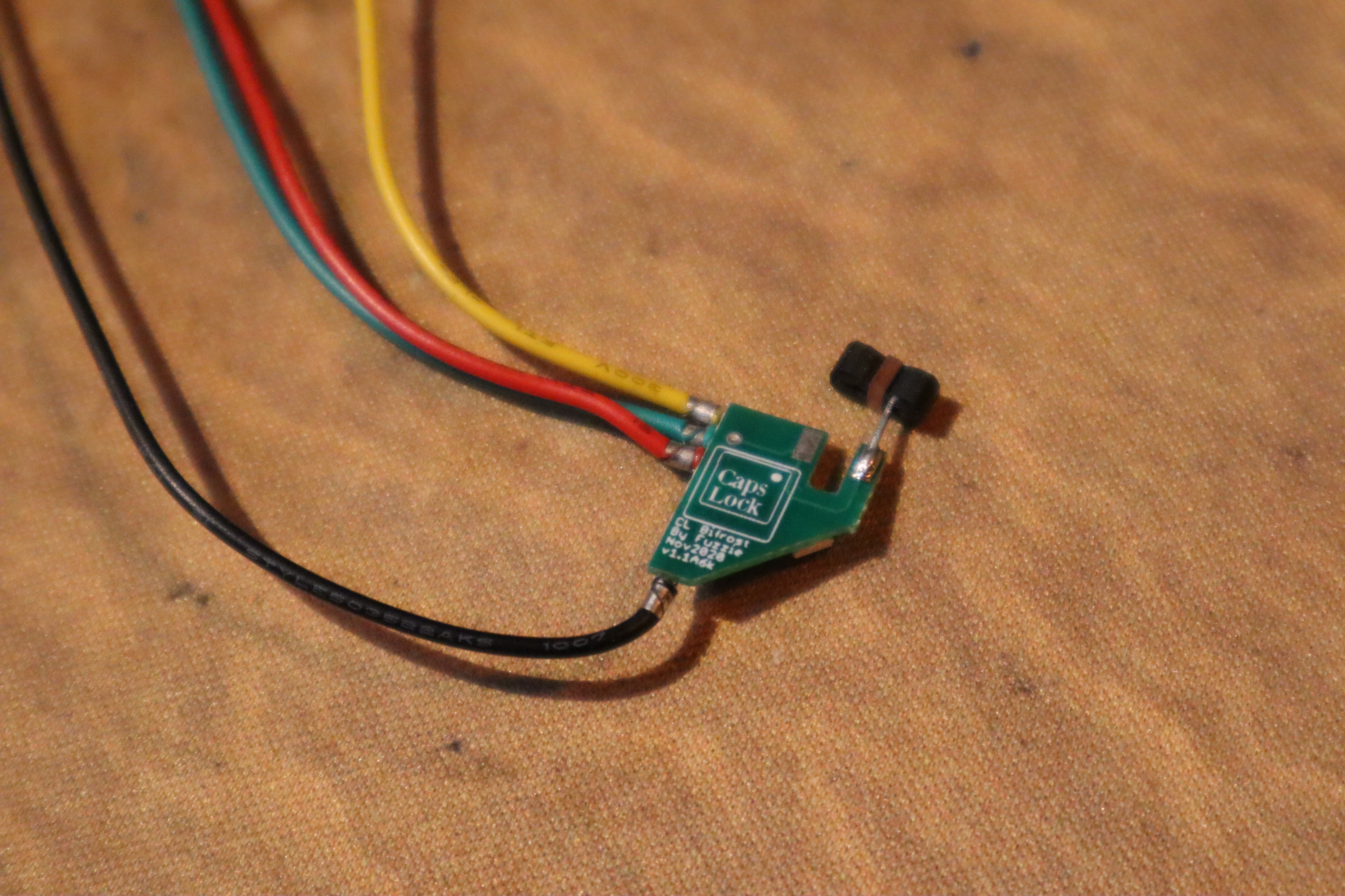
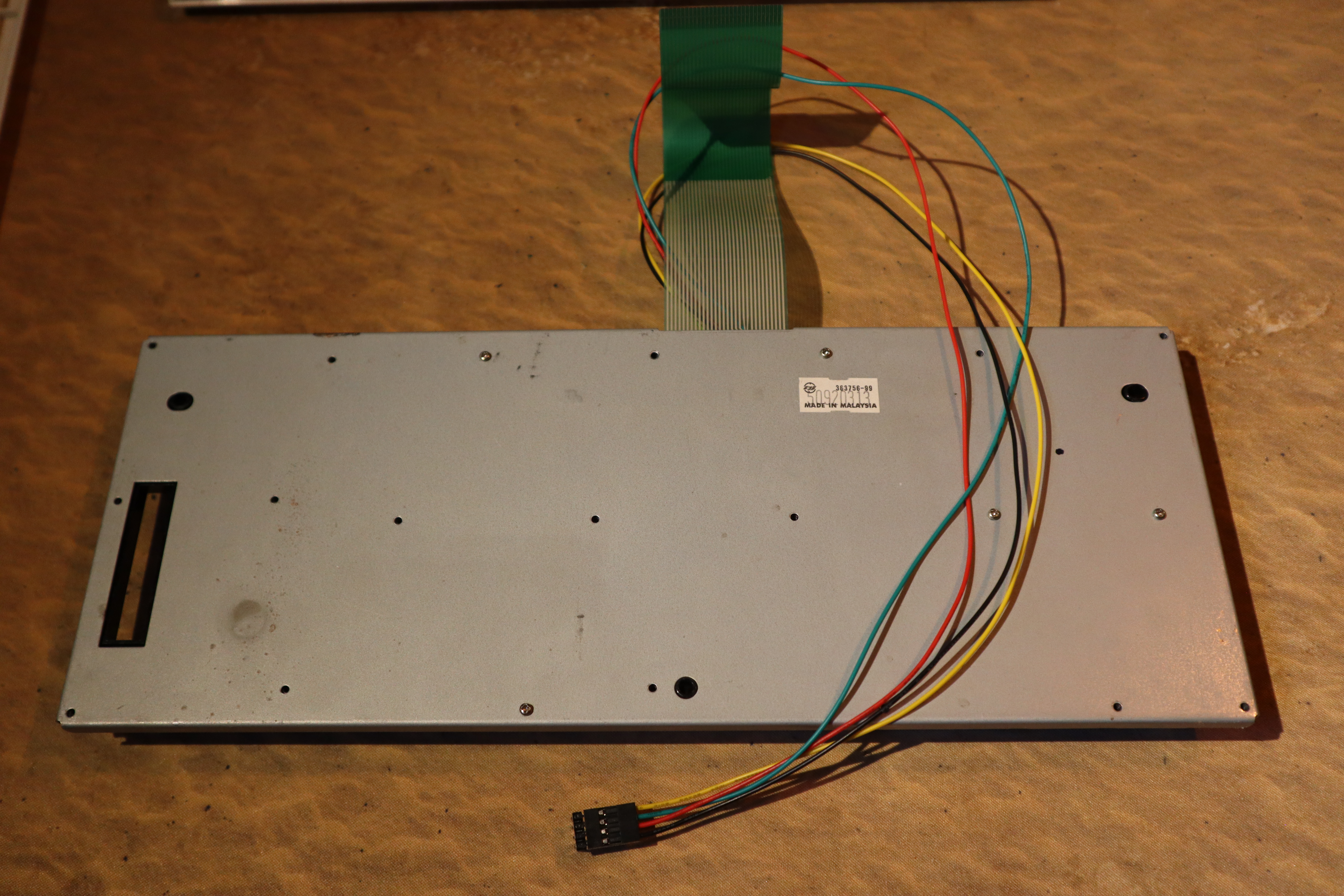
Caps Lock Module (optional)
The CL Module is another optional modification you can perform to your computer. On the keyboard on the CAPS LOCK button there is an
indicator light, usually green or red, that you can replace with this module. With the CL Bifrost you will have the same modification options for that
light as you do for your other ones.
You need to disassemble your keyboard for this: Remove the keyboard from the Amiga, unscrew all the little screws on the backside of it
and lift the keyboard sandwich apart. Pay close attention to how it all fits together!
Now, with only the keyboard frame infront of you turn it around to see the "back" of all the keys. At the Caps Lock key you will find a
small traditional 3mm LED with 90' bent pins going into a rubber signal transfer piece. Take off the small rubber piece gently and slide it
ontop of the pin of the CL Bifrost module instead. As you probably already noticed the CL Bifrost have only one pin instead of the original
LEDs two, so you will be left with one empty hole in the rubber piece. The empty hole should be turned to face inwards towards the CL Bifrost
itself.
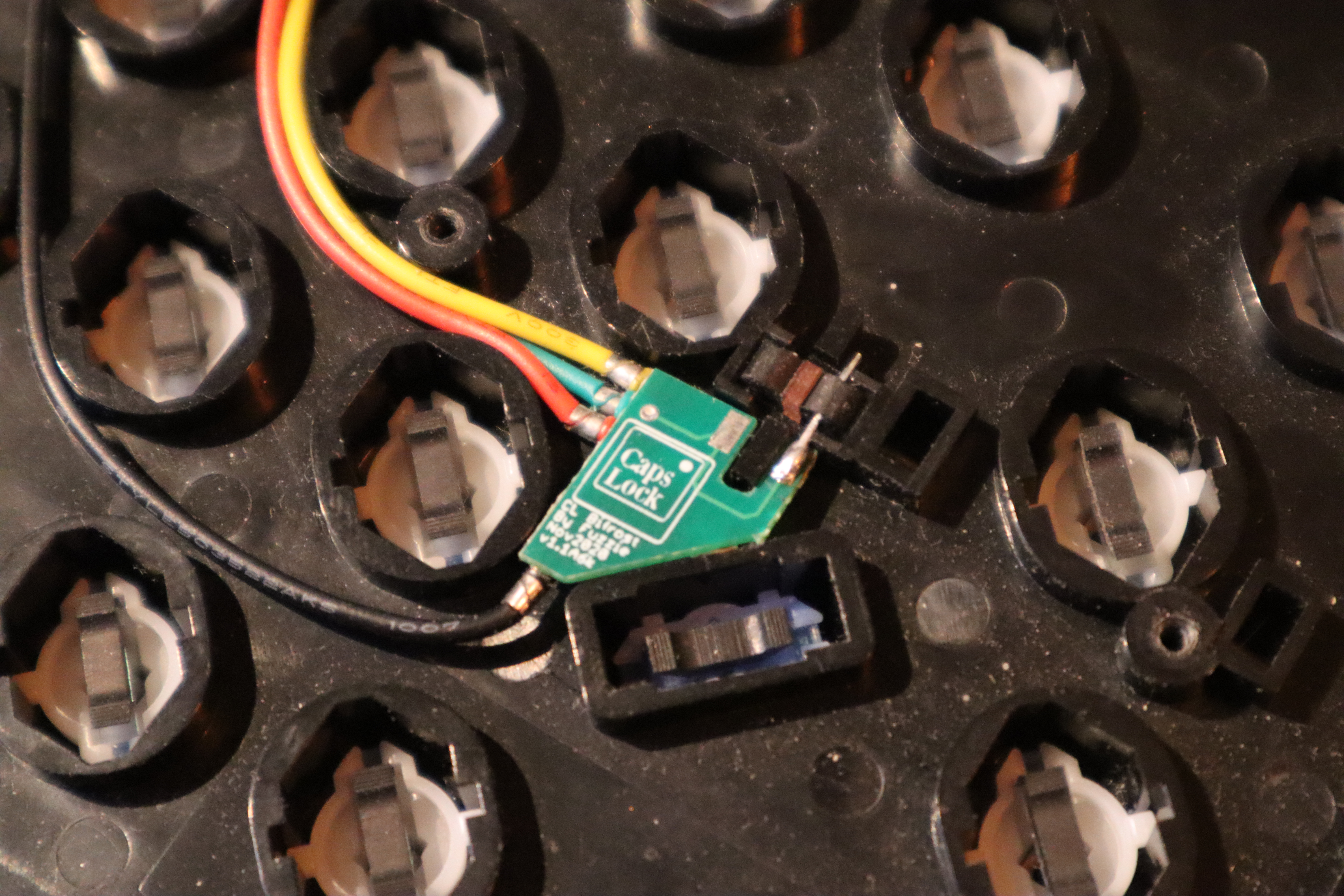
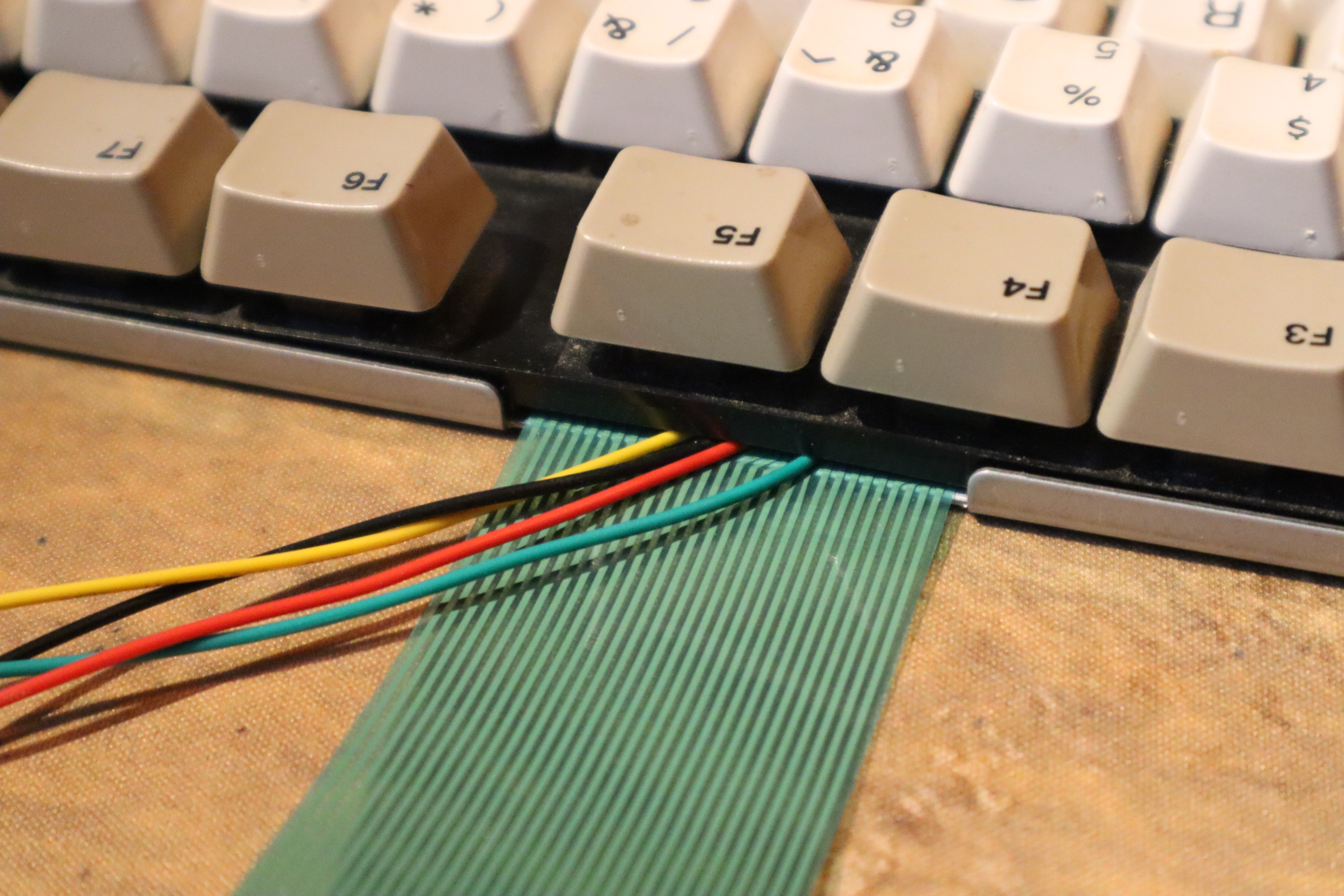
Carefully place the module into the keyboard, aligning the CAPS LOCK hole with the CL Bifrost LED and with the rubber piece back into its
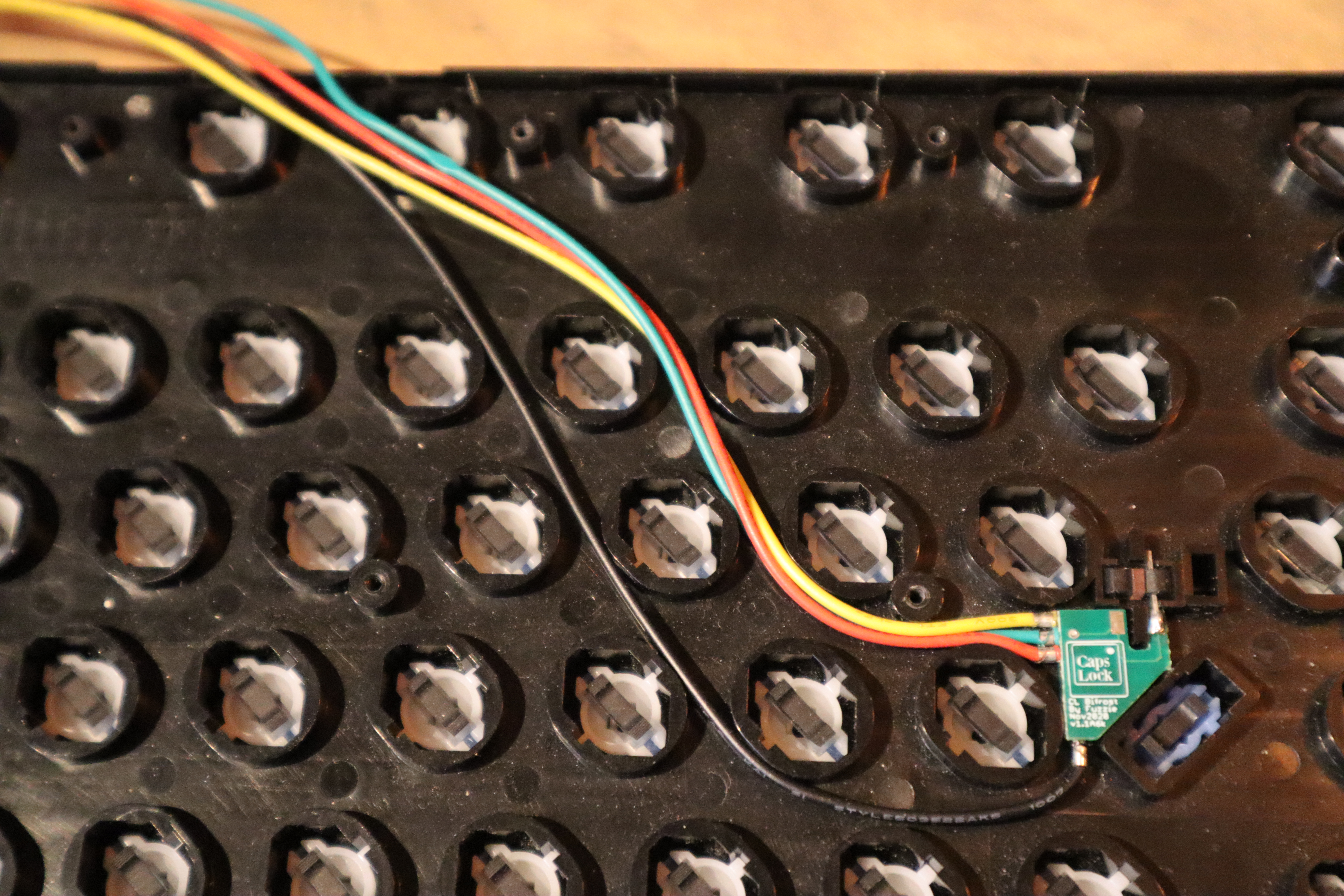
place. Navigate the cables in the empty space between the key collars and up towards and out from the same hole as the keyboard ribbon cable exits
through. Now gently place the green keyboard contact sheet back and sandwich it with the back plate. This whole cable threading procedure is a
bit complicated and time consuming to get right. Make sure all is in place properly and that cables run without being squished anywhere when you
screw the whole sandwich back together.
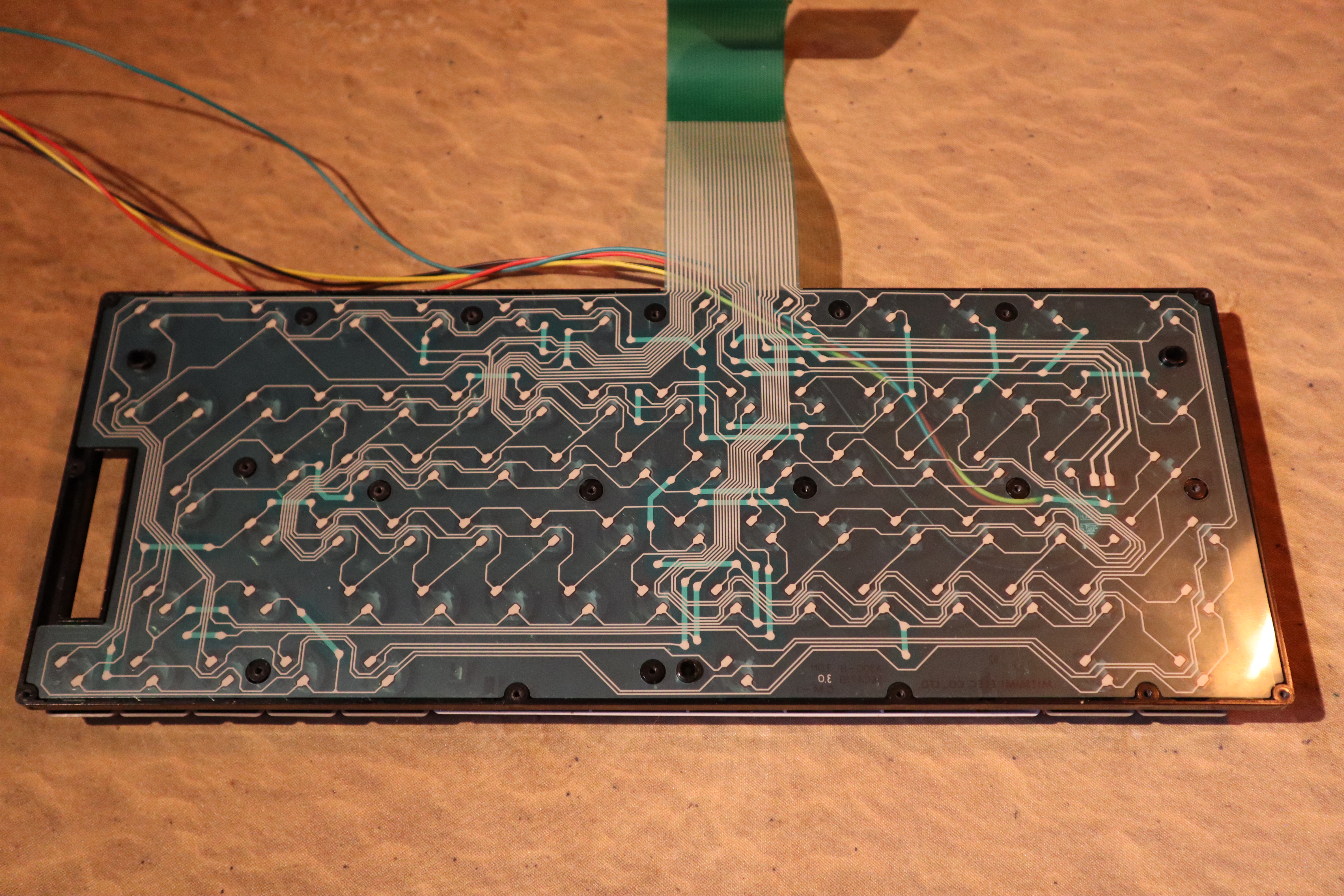
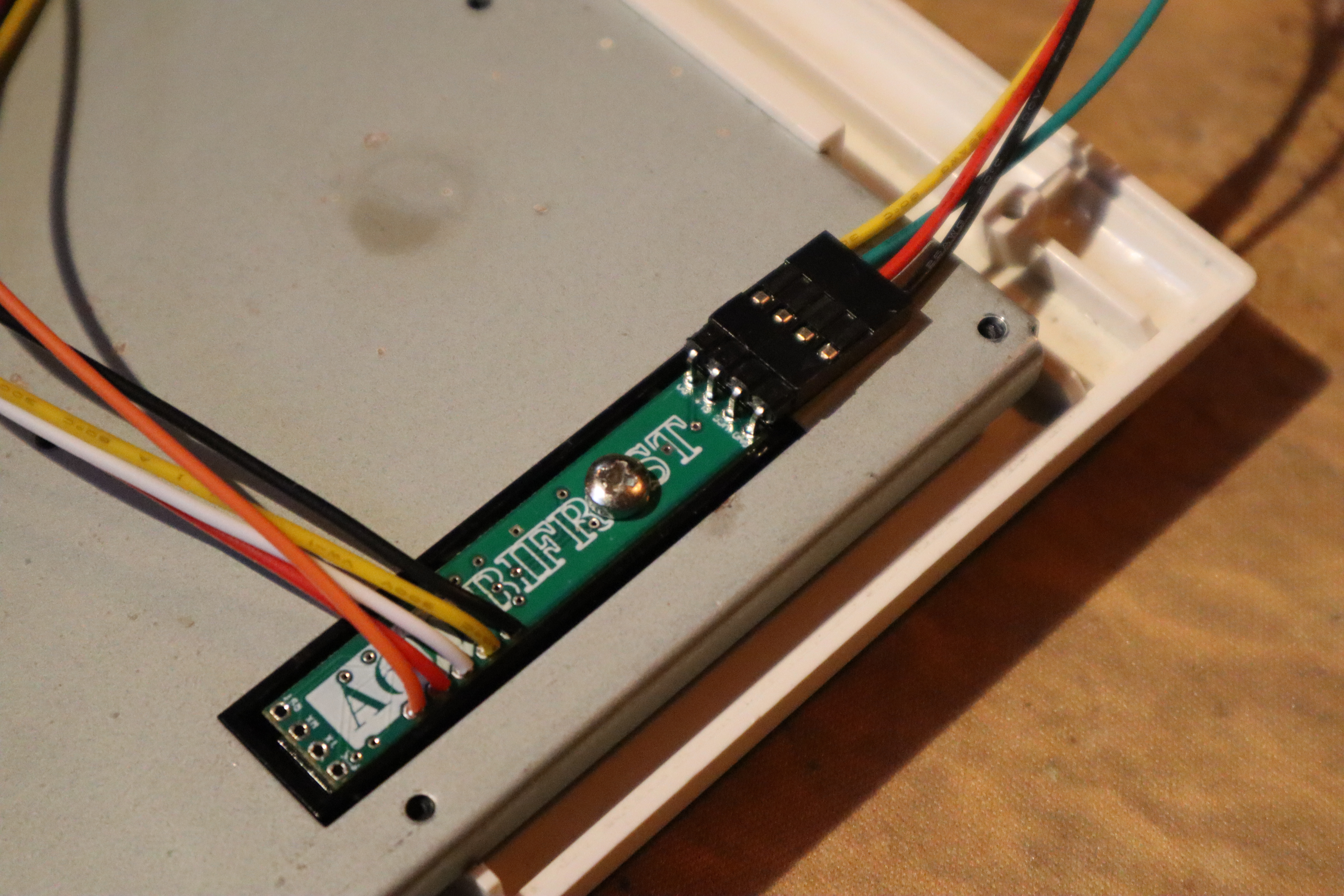
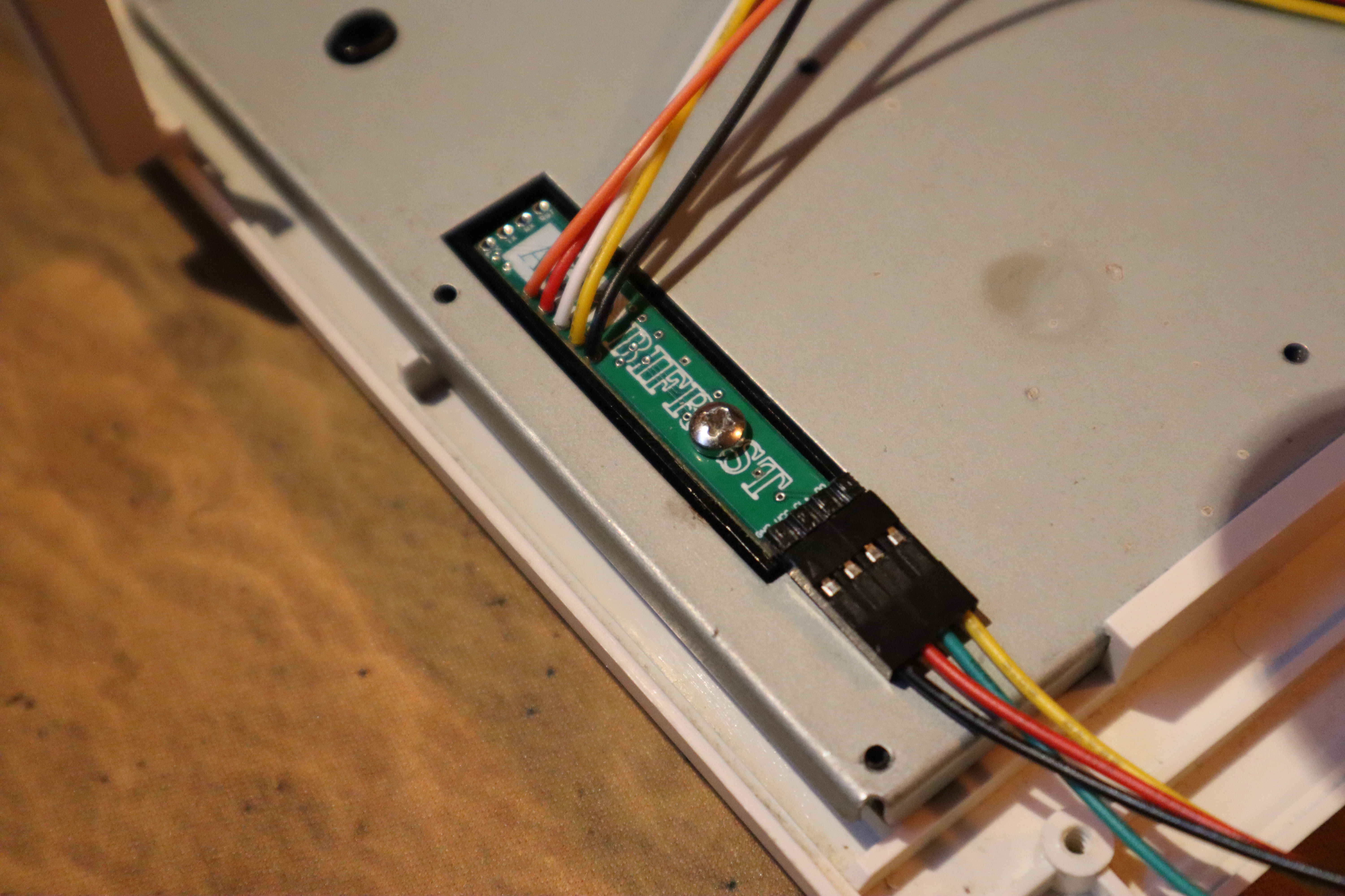
Once the keyboard is assembled back and the CL Bifrost leads go out from the keyboard ribbon cable hole place everything back and connect the
CL Bifrost up to the main Bifrost unit. Use the 90' angled connector already provided with the CL Bifrost to gently press the connector in place as
pictured below. On the main board black goes to Ground, Red goes to +5V, Green goes to CL+ and Yellow goes to DO.
|
|
|
Photos used with expressed permissions. If you want to use any of the pictures please inquiry with the original photographer directly.
"The Bifrost Project" and it's attached products are not endorsed by nor affiliated with the Amiga or Commodore brands, companies, or owners thereof.
The Bifrost Project™, A500 Bifrost™, A600 Bifrost™ and A1200 Bifrost™ names and logotypes are registered and/or worked in IP's 2016-2024 owned by Fuzzie Technologies®.
a500bifrost.com, a600bifrost.com, a1200bifrost.com are registered domains 2017-2024 owned by Fuzzie Technologies®.
Fuzzie Technologies® is a registered company in Sweden since 2013.
|